
Flat plate thin pipe type electrode pole plate

A thin, plate technology, used in lead-acid battery electrodes, electrode carriers/current collectors, etc., can solve the problems of long charging time, small specific energy, and low utilization rate of active materials, and achieve high utilization rate of active materials. specific energy effect

Active Publication Date: 2015-02-04
夏伟绩
View PDF9 Cites 0 Cited by
  • Summary
  • Abstract
  • Description
  • Claims
  • Application Information

AI Technical Summary

Problems solved by technology

[0002] In recent years, with the depletion of primary energy in the world, oil shortage, rising oil prices, and more and more serious environmental pollution, people's awareness of environmental protection has increased. With the increase of strength, there is an urgent need for an energy storage power battery with high specific energy, high specific power, instantaneous super-high current charge and discharge, sealing, maintenance-free, long life and safety, and moderate price. The energy storage batteries used at this stage are very Difficulty satisfying appeal requirements at the same time
The existing lead-acid battery plates are made of paste type, tubular type, etc., according to the cross-section of the casing used in the tubular battery, it can be divided into circular, oval and rectangular tubular plates. Most of the lead core ribs are circular in cross section, the surface area of ​​the lead core and the contact area of ​​the active material are small, the performance of the battery is low in the utilization rate of the active material, the specific energy is small, it cannot be charged and discharged with a large current, and the charging time is long. 12-16 hours, short life, generally 250-750 times

Method used


Image

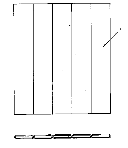
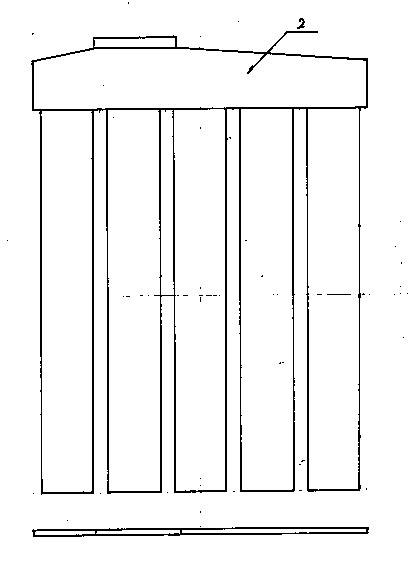
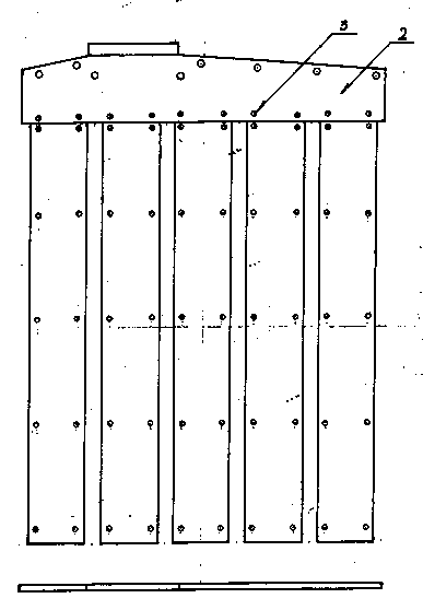
  • Flat plate thin pipe type electrode pole plate
  • Flat plate thin pipe type electrode pole plate
  • Flat plate thin pipe type electrode pole plate

Examples


Embodiment Construction

[0020] The present invention will be further described through the accompanying drawings and typical embodiments below, but the embodiments are only for illustration and cannot limit the scope of the present invention.

[0021] A flat strip-shaped thin tubular electrode plate, including a positive electrode plate, the positive electrode plate is provided with a row tube 1 and a grid 2 sleeved in the row tube 1 and filled between the row tube 1 and the grid 2 The positive electrode mixture 6; the row pipe 1 is a thin flat strip and is set on the grid 2; the grid 2 is composed of several flat strip thin alloy lead strips 8, and the grid 2 is provided with There are several reinforcing rib holes 3, and the reinforcing rib holes 3 are connected by reinforcing ribs 4.

[0022] It also includes connecting ribs 7, which are vertically arranged at the bottom of the grid 2 and sealed by the back cover. When the entire electrode plate is charged and discharged, it can form a whole pl...


PUM

PropertyMeasurementUnit
The inside diameter ofaaaaaaaaaa
Thicknessaaaaaaaaaa

Abstract

The invention provides a flat plate thin pipe type electrode pole plate. The flat plate thin pipe type electrode pole plate comprises a positive pole plate, wherein the positive pole plate is provided with a row pipe, a plate grid arranged in the row pipe in a sleeving manner and a positive pole mixed substance fed between the row pipe and the plate grid. The flat plate thin pipe type electrode pole plate is characterized in that the row pipe is of a thin flat plate strip shape and is arranged on the plate grid; the plate grid is composed of a plurality of flat plate strip-shaped alloy lead strips and is provided with a plurality of reinforcing rib holes; and the reinforcing rib holes are connected by plastic reinforcing ribs. According to the flat plate thin pipe type electrode pole plate, instant large-current discharging can be realized and instant ultra-large-current charging can be realized; the flat plate thin pipe type electrode pole plate is adapted to energy recycling in process of going downhill and braking of electric automobiles; and the service life is a long service life being more than 1400 times, and the utilization rate of active substances is high.

Description

technical field [0001] The invention belongs to the field of battery pole plates, and in particular relates to a flat strip-shaped thin tube-row type electrode pole plate. technical background [0002] In recent years, with the depletion of primary energy in the world, oil shortage, rising oil prices, and more and more serious environmental pollution, people's awareness of environmental protection has increased. With the increase of strength, there is an urgent need for an energy storage power battery with high specific energy, high specific power, instantaneous super-high current charge and discharge, sealing, maintenance-free, long life and safety, and moderate price. The energy storage batteries used at this stage are very It is difficult to meet the appeal requirements at the same time. The existing lead-acid battery plates are made of paste type, tubular type, etc., according to the cross-section of the casing used in the tubular battery, it can be divided into circula...

Claims


Application Information

Patent Timeline
IPC IPC(8): H01M4/73H01M4/14
CPCH01M4/14H01M4/73Y02E60/10
Inventor 夏伟绩
Owner 夏伟绩
Learn More