
Adjustable cutting-depth cutter bar

An adjustable and tool holder technology, which is applied to the accessories of tool holders, tool holders, turning equipment, etc., can solve the problems of low work efficiency and waste of resources, and achieve the effect of simple structure and convenient replacement

Inactive Publication Date: 2015-02-11
ZHENGZHOU BERLT HARD MATERIALS
View PDF8 Cites 1 Cited by
  • Summary
  • Abstract
  • Description
  • Claims
  • Application Information

AI Technical Summary

Problems solved by technology

[0003] The technical problem to be solved by the present invention is that the traditional grooving process wastes resources and has low work efficiency. To provide an adjustable depth-of-cut cutter bar with simple structure, easy replacement, economical and practical, and high work efficiency

Method used


Image

  • Adjustable cutting-depth cutter bar
  • Adjustable cutting-depth cutter bar
  • Adjustable cutting-depth cutter bar

Examples


Embodiment Construction

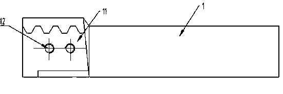
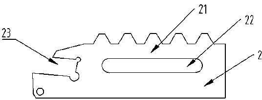
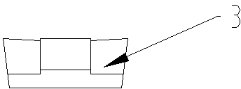
[0020] Such as Figure 4 with Figure 7 As shown, the present invention includes a rod-shaped knife handle 1 connected with a cutter head holder 2 .

[0021] The rod-shaped handle 1 is connected to the cutter head holder 2, which means that the rod-shaped handle 1 and the cutter head holder 2 are fixedly connected through the toothed groove 11 and the toothed bar 21 that cooperate with each other; the toothed groove 11 And the toothed bar 21 can be moved and adjusted to the required length.

[0022] Such as figure 1 with figure 2 As shown, the teeth of the cooperating toothed bar 11 and the toothed groove 21 are arranged on one side of the rod-shaped handle 1 and the bit holder 2 .

[0023] Such as Figure 5 with Image 6 As shown, the cooperating toothed grooves 11 and the teeth of the toothed bar 21 are arranged on both sides of the rod-shaped tool handle 1 and the tool bit holder 2 .

[0024] The tooth shape described is trapezoidal tooth, and other tooth shapes suc...


PUM


Abstract

The invention discloses an adjustable cutting-depth cutter bar, particularly relates to a grooving cutter bar with adjustable cutting depth and solves the technical problems of resource waste and low working efficiency by traditional groove machining. The adjustable cutting-depth cutter bar comprises a rod-shaped cutter handle, and the rod-shaped cutter handle is connected with a cutter head clamping piece. The adjustable cutting-depth cutter bar has the advantages that the structure is simple, the replacement is convenient, the number of cutter handles and relevant components is small, high-quality efficient and economical groove machining can be finished, the cutter head clamping piece can be matched with grooving cutters such as hard alloy coated cutting tools, ceramic cutting tools and polycrystalline cubic boron nitride (PcBN) composite piece welding cutters, and machining of grooves with different cutting depths and different widths can be conveniently achieved by the aid of different cutter head clamping pieces.

Description

technical field [0001] The invention relates to a grooving knife rod, in particular to a grooving knife rod with adjustable cutting depth. Background technique [0002] In the actual groove processing, due to the different shape, distribution, width and depth of the processed grooves, it is often necessary to configure different cutter head holders, which wastes resources, and it takes a certain amount of time to replace these modules during the processing process, resulting in low work efficiency. Contents of the invention [0003] The technical problem to be solved by the present invention is that the traditional grooving process wastes resources and has low work efficiency. It provides a simple structure, convenient replacement, economical, practical and high work efficiency adjustable depth-of-cut cutter bar. [0004] In order to achieve the above object, the present invention adopts the following technical solution: an adjustable depth-of-cut cutter bar, including a r...

Claims


Application Information

Patent Timeline
IPC IPC(8): B23B29/04B23B29/00
CPCB23B29/043B23B29/00
Inventor 刘书锋袁帅
Owner ZHENGZHOU BERLT HARD MATERIALS
Learn More