Heat pump, in particular for heating a vehicle interior, and method for operating a heat pump

A vehicle interior and heat pump technology, which is applied to the operation mode of machines, vehicle components, heat pumps, etc., can solve problems such as high driving energy, and achieve the effects of low driving energy consumption and environmental protection costs

Inactive Publication Date: 2015-02-11
MAN TRUCK & BUS AG
View PDF7 Cites 8 Cited by
  • Summary
  • Abstract
  • Description
  • Claims
  • Application Information

AI Technical Summary

Problems solved by technology

[0004] The thermal efficiency of this known heat pump cycle depends on the compressor power and requires high driving energy

Method used


Image

  • Heat pump, in particular for heating a vehicle interior, and method for operating a heat pump
  • Heat pump, in particular for heating a vehicle interior, and method for operating a heat pump
  • Heat pump, in particular for heating a vehicle interior, and method for operating a heat pump

Examples


Embodiment Construction

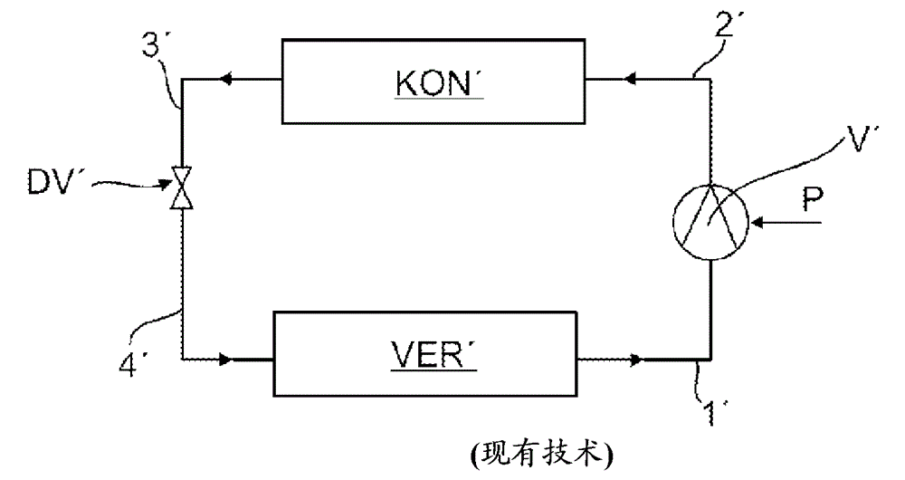
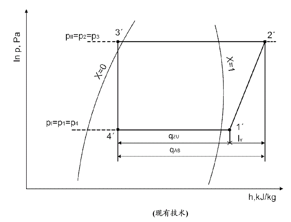
[0047] Figure 4 Diagram showing a left-handed compression / cold vapor cycle process (KKKP) of a heat pump without a jet pump according to the prior art (the reference numbers used are intended to depict both the connecting line and the working medium contained in each case in the connecting line or, and their current state):

[0048] The working medium (coolant) is compressed in a known manner as a superheated fluid in the compressor V' (multiple compression 1'→2') and fed to the condenser KON'. The latent and sensible heat of the fluid (2'→3') is transferred in the condenser KON directly to the vehicle interior, such as the passenger space or the driver's cabin, or indirectly as usable heat to the auxiliary medium circuit of the vehicle. After the phase change in the condenser KON', the working medium is throttled in the subsequent throttle valve DV' (via the Joule-Kelvin effect, 3'→4'). At the end of the throttling process, the working medium achieves the wet steam paramet...


PUM


Abstract

A heat pump for heating a vehicle interior includes a compressor arranged in a heat-pump circuit of a working medium, a condenser, a throttle valve and an evaporator. Gaseous working medium is compressed in the compressor. The compressor outlet is connected to the inlet of the condenser in which the working medium condenses, at the same time discharging heat, the heat being delivered as useful heat directly or indirectly to a consumer. The condenser is followed by a jet pump, to which the liquid working medium coming from the condenser is delivered as driving medium and to which the gaseous working medium flowing out from the evaporator is delivered as suction medium, in such a way that the driving medium and suction medium are compressed in the jet pump as a two-phase mixture. The jet-pump outlet is connected to the inlet of a separator, to which the two-phase mixture is delivered and in which the gaseous working medium is separated from the liquid working medium. The gas outlet of the separator is connected to the compressor inlet and the liquid outlet of the separator is connected to the inlet of the throttle valve, the liquid working medium being throttled in the throttle valve, and the outlet of the throttle valve is connected to the inlet of the evaporator, in which, by the supply of heat, phase transformation takes place to the gaseous working medium.

Description

technical field [0001] The invention relates to a heat pump according to the aforementioned characterizing part of claim 1 , in particular for heating a vehicle interior, and a method for operating a heat pump according to the aforementioned characterizing part of claim 5 . Background technique [0002] For generating cold and heat, the compression / cold vapor cycle process (KKKP) is generally known, the working medium (coolant) used is a hydrocarbon according to DIN 8962. To heat the interior of a vehicle, such as the passenger space or the driver's compartment of a bus, heat pumps have been used in which a left-handed (linksläufiger) compression / cold vapor cycle process (KKKP) is implemented, and the commonly used coolant is R 134a. [0003] In this heat pump cycle, the compressor, condenser, throttle valve and evaporator are arranged in series. The working medium (coolant) is compressed as superheated fluid in the compressor and fed to the condenser, which discharges late...

Claims


Application Information

Patent Timeline
Patent Type & Authority Applications(China)
IPC IPC(8): F25B29/00
CPCF25B2400/23F25B40/00F25B9/008B60H1/3213C09K5/041F25B30/02F25B41/00F25B2341/0012F25B2309/06F25B2341/0011B60H2001/3298B60H1/00F25B30/00
Inventor A.许德洛
Owner MAN TRUCK & BUS AG
Why Eureka
Try Eureka