A magnetic field generation method for testing the dynamic characteristics of giant magnetoresistance sensors

A technology of giant magnetoresistance and dynamic characteristics, which is applied in the field of research on the dynamic characteristics of giant magnetoresistance sensors, can solve the difficult to meet the requirements of high-precision testing of the dynamic characteristics of giant magnetoresistance sensors, and it is difficult to realize the high-frequency dynamic characteristics of giant magnetoresistance sensors. It is not conducive to the research of the dynamic characteristics of giant magnetoresistance sensors and other issues, which is conducive to the improvement and upgrading of the device, is conducive to the dynamic characteristics, and realizes the effect of modular design of the device

Inactive Publication Date: 2016-08-24
BEIHANG UNIV
View PDF5 Cites 0 Cited by
  • Summary
  • Abstract
  • Description
  • Claims
  • Application Information

AI Technical Summary

Problems solved by technology

[0005] (1) Due to the influence of inductance, the existing dynamic magnetic field generation method cannot generate a dynamic magnetic field with a wider frequency, and it is difficult to realize the high-frequency dynamic characteristic test of the giant magnetoresistive sensor
[0006] (2) The existing dynamic magnetic field measurement methods, due to their own shortcomings, are difficult to meet the requirements of high-precision testing of the dynamic characteristics of giant magnetoresistance sensors, which is not conducive to the research of dynamic characteristics of giant magnetoresistance sensors

Method used


Image

  • A magnetic field generation method for testing the dynamic characteristics of giant magnetoresistance sensors
  • A magnetic field generation method for testing the dynamic characteristics of giant magnetoresistance sensors
  • A magnetic field generation method for testing the dynamic characteristics of giant magnetoresistance sensors

Examples


Embodiment Construction

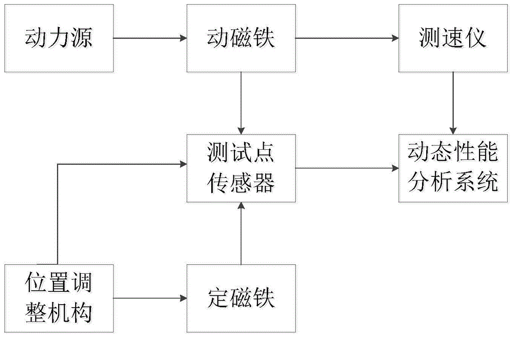
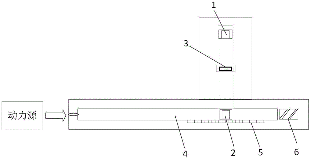
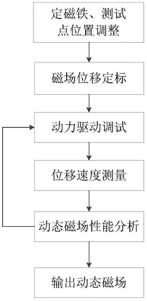
[0028] Such as figure 1 , 3 As shown, the present invention is a method for generating a magnetic field for the dynamic characteristic test of a giant magnetoresistance sensor. The specific steps of the method are as follows:

[0029] Step 1: The dynamic magnetic field method of the present invention adopts two permanent magnets as the magnetic field output source, such as figure 2 As shown; first place the fixed magnet (1) and the moving magnet (2) facing each other, then keep the position of the moving magnet (2) unchanged, adjust the front and rear positions of the fixed magnet (1), and change the relative distance between the two permanent magnets , the test point (3) is always placed in the middle of the fixed magnet (1) and the moving magnet (2), so as to realize the adjustment of the magnetic field strength range of the test point; use a high-precision Tesla meter to measure the magnetic field strength at the test point (3) value, and then determine the relative dist...


PUM


Abstract

The invention provides a magnetic field generating method used for the dynamic feature test of a giant magnetoresistance sensor. The method comprises the following steps that 1, the axial space of magnets and the test point position are determined by two permanent magnets; 2, a displacement scale plate is arranged along a catheter, a movable magnet is moved for measuring the magnetic field intensity of the test point, and a function relationship H(s) between the relative displacement of the movable magnet and the magnetic field intensity is built; 3, a power source is used for driving the movable magnet, and the dynamic magnetic field with the magnetic field intensity changed along with the time is generated; 4, a laser speed measuring instrument is arranged on the side surface of the catheter, the moving speed of the movable magnet in the catheter is measured in real time, and the function relationship s(t) between the relative displacement and the time is built; 5, the s(t) and the H(s) are used for deducing and building a mathematic model Ht(t) with the dynamic magnetic field changed along with the time, and the magnetic field quantity measurement direction displacement measurement conversion is realized; 6, the power dimension of the power source is changed, and the dynamic magnetic field meeting the dynamic characteristic test requirements of the giant magnetoresistance sensor is generated. The method has the advantages that the modularized design of the device is realized, and the device can be favorably improved and upgraded.

Description

technical field [0001] The invention relates to a magnetic field generating method for testing the dynamic characteristics of a giant magnetoresistance sensor, which can generate a magnetic field suitable for testing the dynamic characteristics of the giant magnetoresistance sensor, and can test the performance index of the giant magnetoresistance sensor. It belongs to the technical field of research on dynamic characteristics of giant magnetoresistance sensors. Background technique [0002] The magnetic field is the most basic physical quantity in nature, and the measurement of many physical quantities is realized based on the change of the magnetic field. As an important part of the magneto-sensitive sensor family, giant magnetoresistive sensors have been widely used in aerospace, biomedicine, modern transportation and other fields, and the research on their characteristics has gradually attracted people's attention. However, due to the limitations of test conditions and ...

Claims


Application Information

Patent Timeline
Patent Type & Authority Patents(China)
IPC IPC(8): G01D18/00H01F7/02
Inventor 邓永富钱政赵晓东田园王婧怡
Owner BEIHANG UNIV
Why Eureka
Try Eureka