Mask plate fixation device and method
A technology for fixing devices and reticles, which is applied in the field of photolithography, can solve problems such as residues, affecting the upper and lower plates of the reticle, and increasing the risk of damage to the reticle carrier, so as to achieve the effect of improving safety and reducing friction
- Summary
- Abstract
- Description
- Claims
- Application Information
AI Technical Summary
Problems solved by technology
Method used
Image

Examples
Embodiment 1
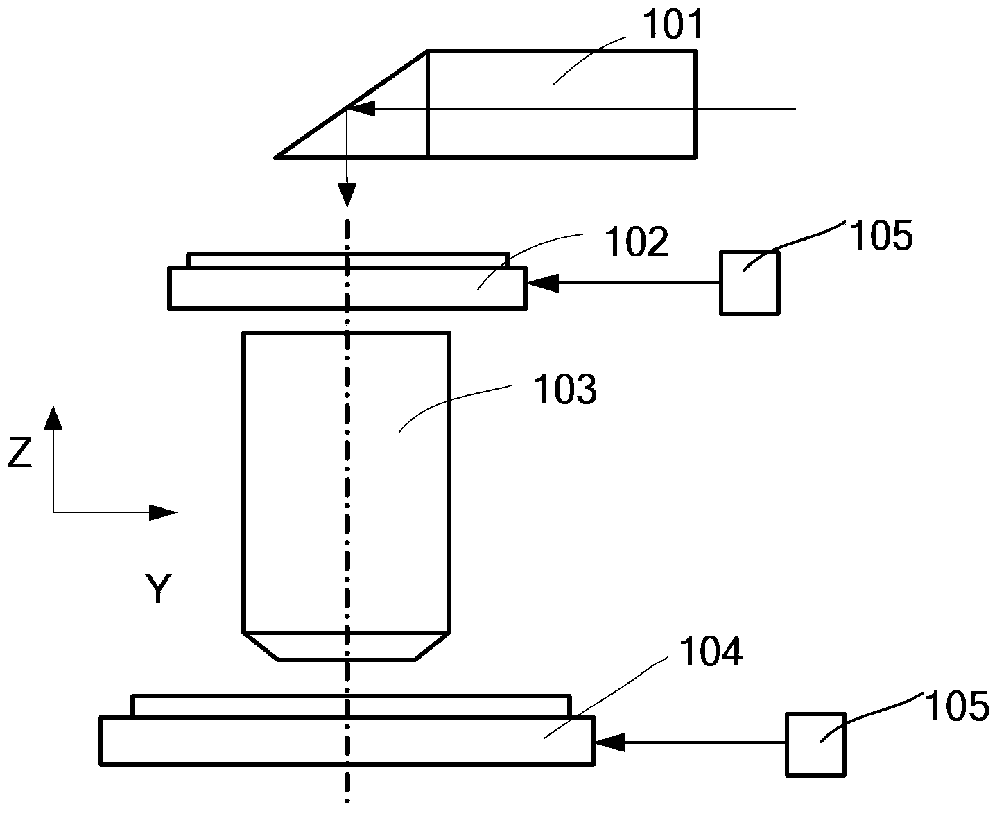
[0042] see figure 1 , which is a schematic diagram of the structure of the photolithography device. It can be seen from the figure that the lithography apparatus mainly includes an illumination system 101 , a mask table 102 , a projection objective lens 103 , a workpiece table 104 , and a laser interferometer 105 . The illumination system 101 provides an exposure light source for the exposure device, the mask table 102 supports and positions the reticle through a mask fixing device (not shown), and the projection objective lens 103 provides an exposure field of view to expose the pattern on the reticle on the glass substrate. The workpiece table 104 carries glass substrates or silicon wafers, and provides support and positioning functions for the glass substrates or silicon wafers. Laser interferometer 105 provides position signals for precise motion control of the mask stage and workpiece stage.
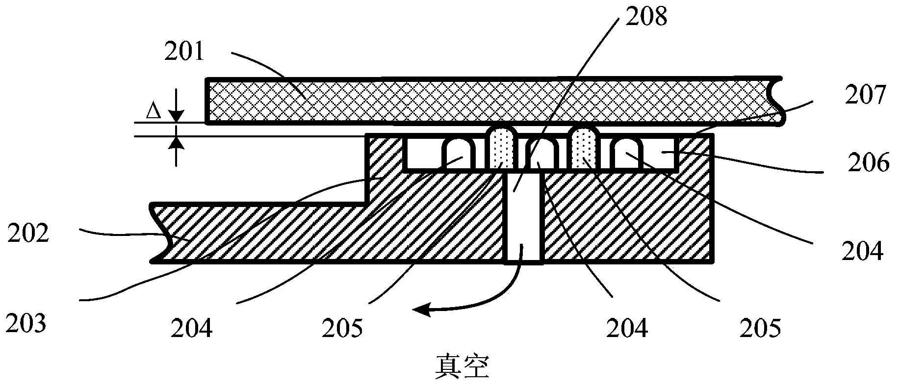
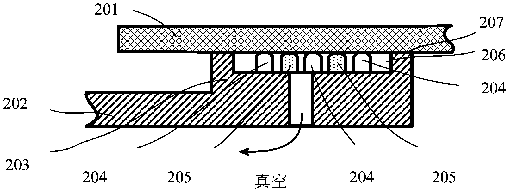
[0043] see Figure 2A and Figure 2B ,in Figure 2A It is a schematic str...
Embodiment 2
[0047] see Figure 3A and Figure 3B ,in Figure 3A It is a schematic structural diagram of the mask fixing device in Embodiment 2 of the present invention (the vacuum is not turned on), Figure 3B It is a schematic structural diagram of the mask fixing device in Embodiment 2 of the present invention (after the vacuum is turned on). The difference between this embodiment and Embodiment 1 is that the flexible device includes a rigid pin 3051 and a flexible pad 3052, and the flexible pad 3052 passes through A coating or coating process is formed on the top of the rigid pin 3051 . The materials of the rigid columns 304 and the rigid pins 3051 are generally the same as those of the plate holder 302 , and they may be integrally processed with the vacuum chamber 306 through mechanical processing or other processes. The material of the flexible pad 3052 is generally a soft elastic material such as rubber, and the flexible material can be fixed on the rigid pin 3051 by coating or c...
Embodiment 3
[0049] see Figure 4A and Figure 4B ,in Figure 4A It is a schematic structural diagram of the mask fixing device in Embodiment 3 of the present invention (the vacuum is not turned on), Figure 4B It is a schematic structural diagram of the mask fixing device in Embodiment 3 of the present invention (after the vacuum is turned on). The difference between this embodiment and Embodiment 1 is: optional, the flexible device is a linear flexible wall 405, optional The flexible wall 405 is in an "S" shape, and the two ends of the flexible wall respectively abut against the bottom of the vacuum chamber and the lower surface of the reticle, that is, by fixing the flexible wall 405 in the plate vacuum chamber 406 A flexible device is thus formed. The flexible wall 405 is arranged between the two rigid columns 404 , and the upper surface of the rigid column 404 is coplanar with the mask adsorption surface 407 of the plate holder boss 403 , serving as the positioning surface of the r...
PUM
| Property | Measurement | Unit |
|---|---|---|
| thickness | aaaaa | aaaaa |
Abstract
Description
Claims
Application Information
 - R&D
- Intellectual Property
- Life Sciences
- Materials
- Tech Scout
- Unparalleled Data Quality
- Higher Quality Content
- 60% Fewer Hallucinations
Browse by: Latest US Patents, China's latest patents, Technical Efficacy Thesaurus, Application Domain, Technology Topic, Popular Technical Reports.
© 2025 PatSnap. All rights reserved.Legal|Privacy policy|Modern Slavery Act Transparency Statement|Sitemap|About US| Contact US: help@patsnap.com