Antenna unit, antenna array and road side unit
An antenna unit and antenna array technology, which is applied to antenna unit combinations, antennas, slot antennas and other directions with different polarization directions, can solve the problem of narrowing the beam width of the RSU antenna, achieve stable circular polarization characteristics, improve impedance bandwidth and Axial ratio bandwidth, effect of radiation stabilization
- Summary
- Abstract
- Description
- Claims
- Application Information
AI Technical Summary
Problems solved by technology
Method used
Image
Examples
Embodiment 1
[0035] like Figure 4 and Figure 5 As shown, the antenna unit of this embodiment includes a first dielectric board 10 and a second dielectric board 20 . The first dielectric plate includes an upper surface, a lower surface and a radiation patch 101 , and the radiation patch 101 can be attached to the upper surface or the lower surface of the first dielectric plate 10 . Figure 4 Shown is a preferred way, that is, the radiation patch 101 is attached to the lower surface. The second dielectric plate 20 includes a first surface 201 opposite to the lower surface of the first dielectric plate and a second surface opposite to the first surface 201 . The radiation patch can be a thin metal sheet, such as a copper sheet.
[0036]The first surface 201 is a plate made of conductive material, which is a metal grounding plate, and a plurality of coupling slots 204 for forming a multi-feed point feeding mode are opened on the first surface, and each coupling slot 204 is concave, or It...
Embodiment 2
[0041] like Image 6 As shown, based on the antenna unit of Embodiment 1, an antenna array proposed in this embodiment includes: a plurality of antenna units 42 arranged at intervals in rows and columns and a plurality of control switches 41, wherein the antenna array can be n rows and m columns, n and m are positive integers, for example Image 6 6 rows x 4 columns are shown. The antenna units in each column are connected in parallel, and the transmission lines thereof constitute the feeding network 43 , which may be composed of transmission lines such as microstrip lines, striplines, and coplanar waveguide wires as required. Moreover, the feed amplitudes of each column of antenna elements are designed according to the Chebyshev distribution, and the phases are kept in phase. Each column of antenna elements is controlled by a control switch, and no switches are used between the antenna elements, that is, individual control switches The number is the same as the number of co...
Embodiment 3
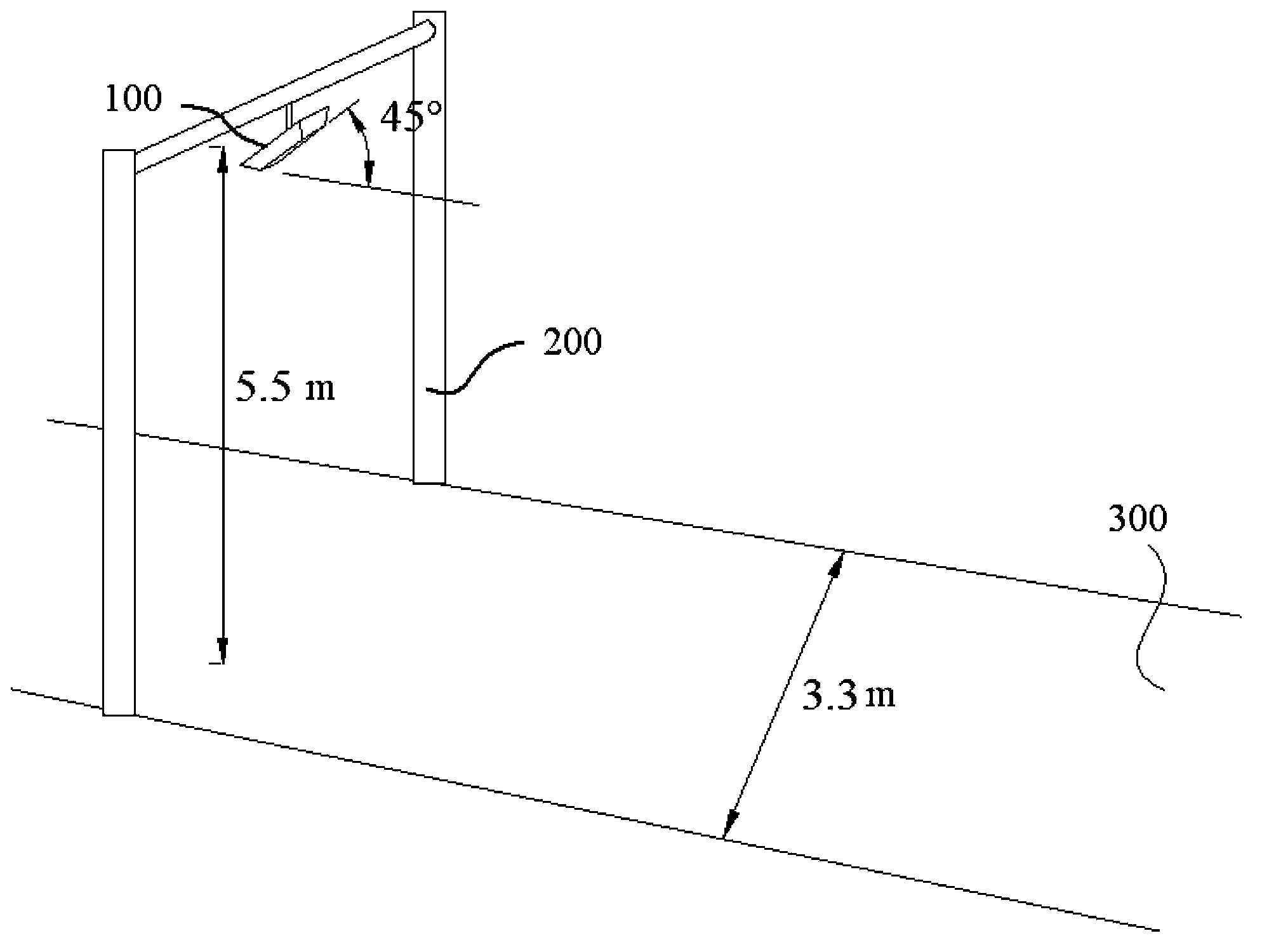
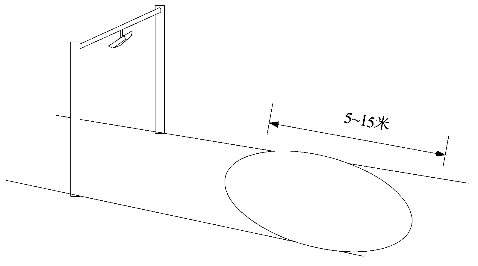
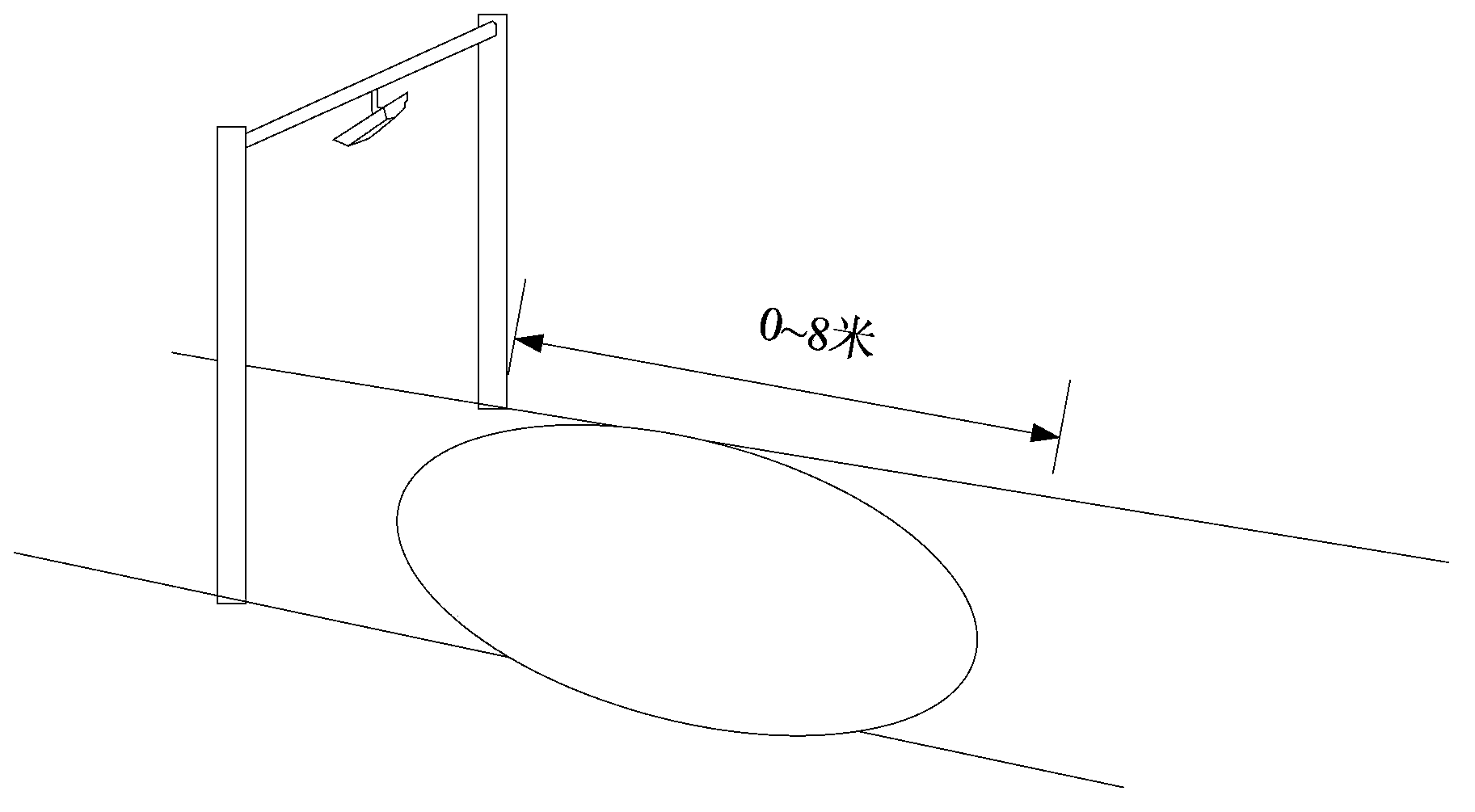
[0047] This embodiment provides a roadside unit, such as Figure 11 As shown, a position detector 80 , a communication area controller 90 and an antenna array 40 are included. Wherein, the antenna array 40 is the antenna array provided in the foregoing embodiments, which will not be repeated. The position detector 80 can be pre-set at different positions of the lane, which can be a ground induction coil or other forms of position sensors. When the vehicle enters the position where the position sensor is installed, the position sensor at this position is triggered to obtain the position information of the vehicle. , the position information of the vehicle can be the specific position coordinates of the vehicle on the lane, for example, the position coordinates take the vertical projection position of the RSU on the lane as the origin of the coordinates, including the horizontal (perpendicular to the lane extension direction) coordinate values and the longitudinal (to the lane...
PUM
| Property | Measurement | Unit |
|---|---|---|
| Thickness | aaaaa | aaaaa |
| Thickness | aaaaa | aaaaa |
| Thickness | aaaaa | aaaaa |
Abstract
Description
Claims
Application Information
 - R&D
- Intellectual Property
- Life Sciences
- Materials
- Tech Scout
- Unparalleled Data Quality
- Higher Quality Content
- 60% Fewer Hallucinations
Browse by: Latest US Patents, China's latest patents, Technical Efficacy Thesaurus, Application Domain, Technology Topic, Popular Technical Reports.
© 2025 PatSnap. All rights reserved.Legal|Privacy policy|Modern Slavery Act Transparency Statement|Sitemap|About US| Contact US: help@patsnap.com


