Continuous oil pipe hanger for velocity tubular column

A technology of tubing hanger and velocity string, which is applied in wellbore/well parts, earthwork drilling and production, etc. It can solve the problem that the coiled tubing velocity string hanger cannot seal the bottom hole pressure and the coiled tubing velocity string hanger cannot realize Suspended tubing, coiled tubing speed string hanger can not achieve sealing and other problems, to avoid oil and gas leakage problems, reduce production and operation time, and achieve high sealing reliability

Active Publication Date: 2015-02-18
JEREH ENERGY SERVICES
View PDF6 Cites 118 Cited by
  • Summary
  • Abstract
  • Description
  • Claims
  • Application Information

AI Technical Summary

Problems solved by technology

[0004] The coiled tubing speed string hanger cannot seal the bottom hole pressure, and the annulus of the coiled tubing speed string hanger cannot be sealed, leaving hidden dangers for operation safety
[0005] The coiled tubing speed string hanger cannot realize the function of hanging the tubing; the coiled tubing slides upward under the action of the bottom hole pressure, which makes it impossible to implement the coiled tubing operation process and leaves hidden dangers for the safe operation of the wellhead

Method used


Image

  • Continuous oil pipe hanger for velocity tubular column
  • Continuous oil pipe hanger for velocity tubular column
  • Continuous oil pipe hanger for velocity tubular column

Examples


Embodiment Construction

[0027] The principles and features of the present invention are described below in conjunction with the accompanying drawings, and the examples given are only used to explain the present invention, and are not intended to limit the scope of the present invention.

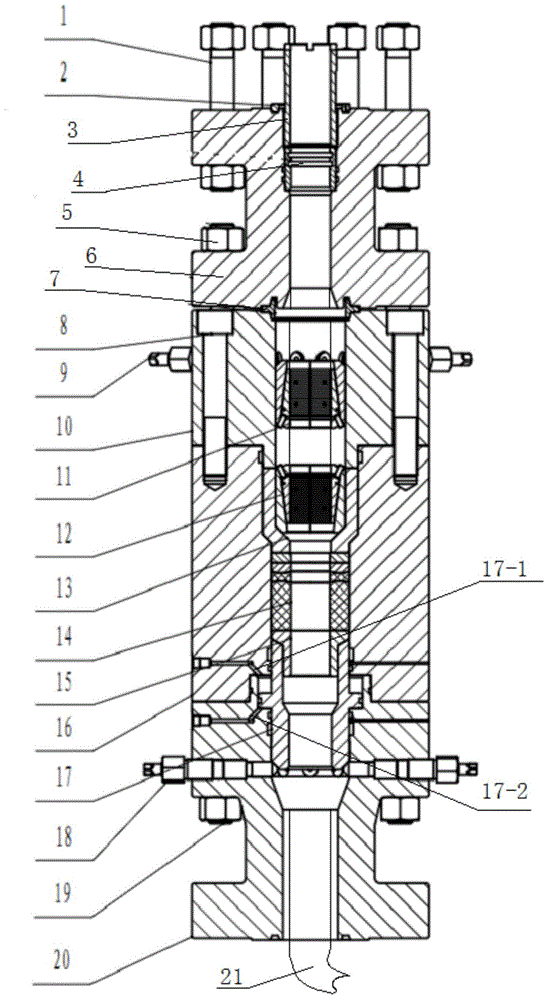
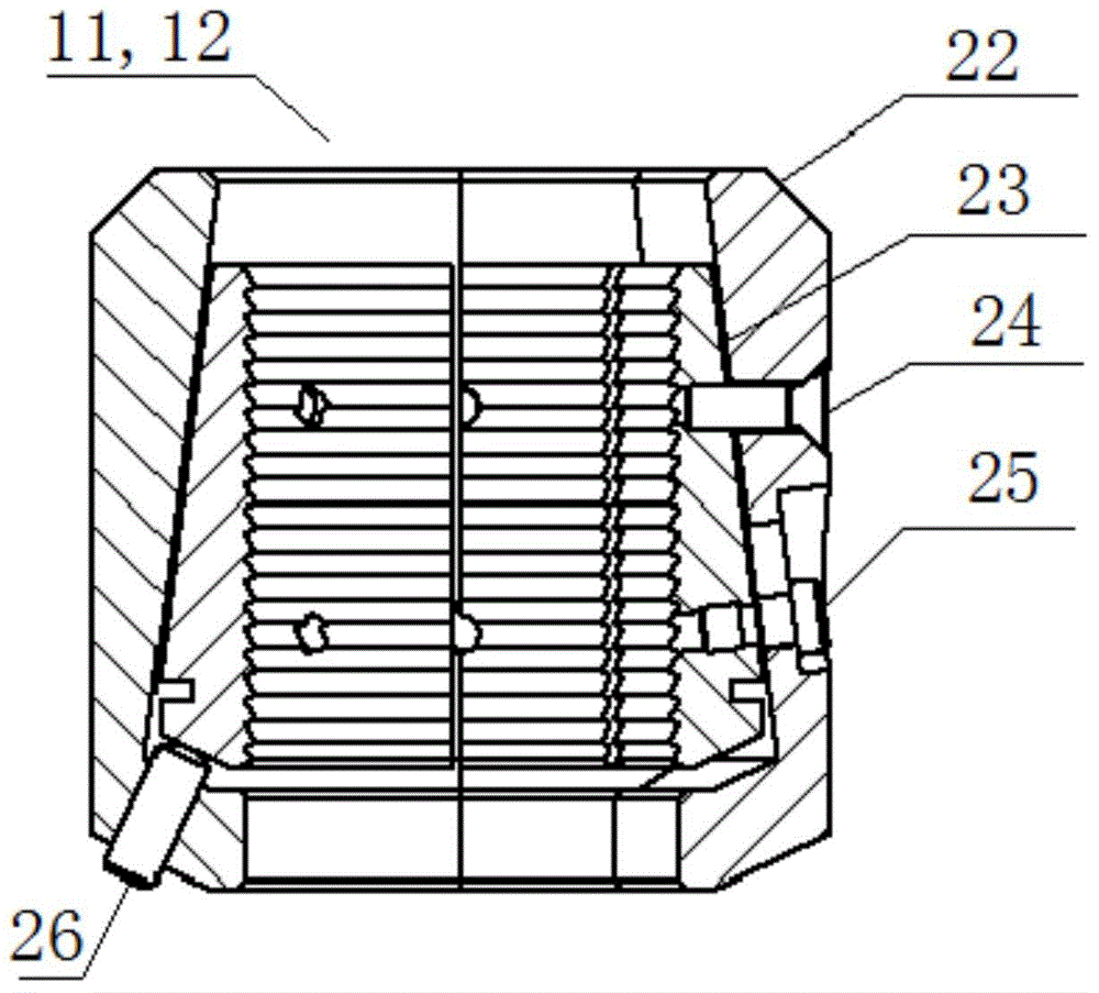
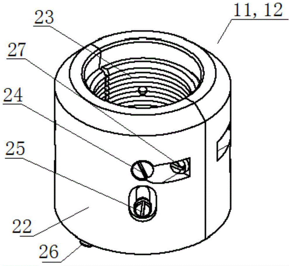
[0028] Such as figure 1 As shown, a velocity string coiled tubing 21 hanger, including coiled tubing 21 and I-shaped flange 6, also includes upper slip assembly 11, lower slip assembly 12, upper shell 10, middle shell 16 And the lower casing 20, the upper casing 10, the middle casing 16 and the lower casing 20 are arranged vertically from top to bottom in turn and are provided with a middle hole through up and down, the I-shaped flange 6, the upper casing 10, the middle The middle holes of the casing 16 and the lower casing 20 are arranged facing each other, and the I-shaped flange 6 is fixedly arranged on the top of the upper casing 10, and is sealed by a gasket 7, and the middle hole of the I-shaped flange 6 is co...


PUM


Abstract

The invention relates to a continuous oil pipe hanger for a velocity tubular column. The continuous oil pipe hanger comprises a continuous oil pipe, an I-shaped flange, an upper slip assembly, a lower slip assembly, an upper shell, a middle shell and a lower shell, wherein vertically penetrating central holes are formed in the upper shell, the middle shell and the lower shell; the I-shaped flange is fixedly arranged at the top of the upper shell; the continuous oil pipe passes through the I-shaped flange and the central holes of the upper shell, the middle shell and the lower shell in turn; the upper slip assembly is clamped on an inner wall of the central hole of the upper shell; the lower slip assembly is located in the central hole of the middle shell; a connecting pipe sealing set is fixedly arranged on an inner wall of the central hole of the middle shell and the lower side of a hanging supporting sleeve; at least one pair of driving pistons is arranged on the inner walls of the central holes of the middle shell and the lower shell and under the connecting pipe sealing set; an upper oil port and a lower oil port respectively communicated with the driving pistons are arranged on the side walls of the middle shell and the lower shell. The continuous oil pipe hanger has the beneficial effect of capability of hanging the continuous oil pipe.

Description

technical field [0001] The invention relates to a coiled tubing speed string operation auxiliary equipment, in particular to a speed string coiled tubing hanger. Background technique [0002] In the middle and late stages of production of water-producing gas wells, due to the decrease in production layer pressure and the increase in water volume, the produced water cannot be discharged in time, thereby reducing the production of gas wells, and even causing wells to be crushed to death. Coiled tubing velocity string drainage gas recovery technology is to lower the tubing with smaller diameter under the condition of underbalance in the original well and hang it at the wellhead. Increase, the high-speed gas flow can greatly enhance the carrying capacity of the produced fluid, which can effectively slow down the water breakthrough time of the gas well. This technology has the advantages of short construction time, quick production increase, long production cycle, and avoiding d...

Claims


Application Information

Patent Timeline
Patent Type & Authority Applications(China)
IPC IPC(8): E21B23/01
CPCE21B23/01
Inventor 苏贵杰梅俊叶登胜
Owner JEREH ENERGY SERVICES
Why Eureka
Try Eureka