LNG dispenser

A gas dispenser and gas phase technology, applied in mechanical equipment, fixed-capacity gas storage tanks, gas/liquid distribution and storage, etc., can solve the problem that the third check valve has no functional significance, shortens the service life of equipment, and inconveniences equipment Maintenance and repair and other issues, to achieve the effect of convenient follow-up maintenance and repair, shortening the required time, and low manufacturing cost

Inactive Publication Date: 2015-02-18
WUXI TEHUI ENERGY EQUIP
View PDF8 Cites 2 Cited by
  • Summary
  • Abstract
  • Description
  • Claims
  • Application Information

AI Technical Summary

Problems solved by technology

[0004] But this kind of liquefied natural gas filling machine has the following disadvantages: the position of the third check valve has no practical functional significance, the internal structure of the filling machine is generally complicated, and the electrical equipment and mechanical process parts are intersected inside the filling machine. The layout is chaotic, which not only shortens the operating life of the equipment, but also makes it difficult to maintain and repair the equipment, and the metering of the return air is not realized under this process condition

Method used


Image

  • LNG dispenser

Examples


Embodiment Construction

[0013] The preferred embodiments of the present invention will be described below in conjunction with the accompanying drawings. It should be understood that the preferred embodiments described here are only used to illustrate and explain the present invention, and are not intended to limit the present invention.

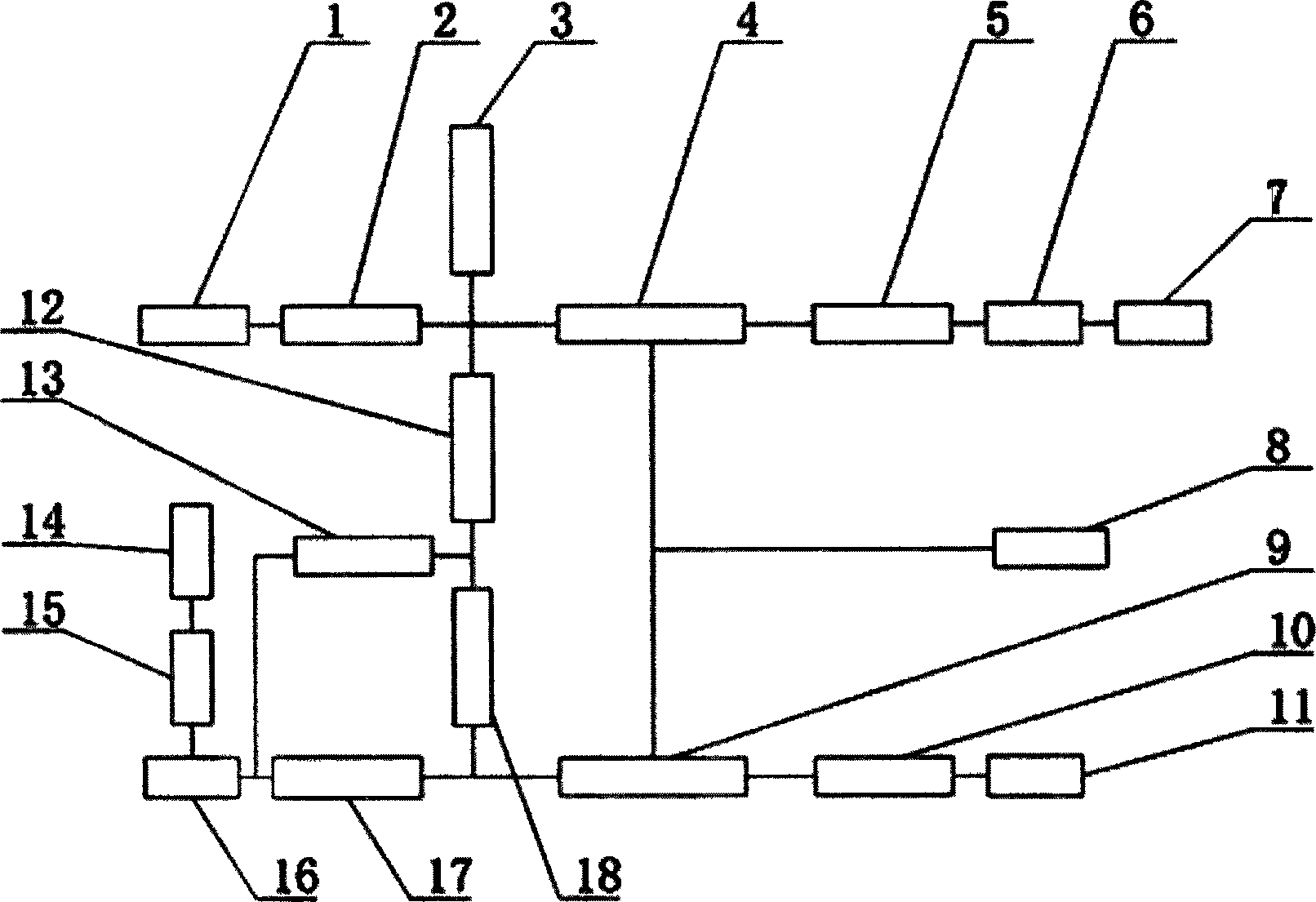
[0014] Such as figure 1 As shown, a LNG filling machine includes a liquid filling pipeline and a return gas return pipeline. One side of the liquid filling pipeline is provided with a liquid inlet 11, and the liquid inlet 11 is connected to the first check valve 10. The first The check valve 10 is connected to the liquid-phase mass flowmeter 9, the liquid-phase mass flowmeter 9 is connected to the first pneumatic valve 17, the first pneumatic valve 17 is connected to the pull-off valve 16, the pull-off valve 16 is connected to the liquid outlet 15, and the liquid outlet 15 Connect the liquid filling gun 14, and install the air return gun 7 on one side of the air ret...


PUM


Abstract

The invention discloses an LNG (Liquefied Natural Gas) dispenser which comprises a liquid addition pipeline and a gas and liquid return pipeline, wherein a liquid inlet is formed in one side of the liquid addition pipeline, and is connected with a first check valve; the first check valve is connected with a liquid phase mass flow meter; the liquid phase mass flow meter is connected with a first pneumatic valve; the first pneumatic valve is connected with a breakaway valve. According to the LNG dispenser, a fourth check valve is additionally arranged on a connecting pipeline of the liquid addition pipeline and the gas and liquid return pipeline on the basis of a conventional process, a check valve originally arranged at a gas and liquid return port is eliminated, and meanwhile, a structural layout is zoned and optimized to shorten the distance between the mass flow meter and the valve, so that a pre-cooling process of the liquid addition pipeline can be faster implemented before the gas adding of the dispenser, and time for the whole gas adding process is further shortened.

Description

technical field [0001] The invention relates to a gas dispenser, more precisely an LNG gas dispenser. Background technique [0002] LNG is liquefied natural gas, which is obtained by compressing and heating up natural gas after purification, cooling and removing heat under the action of mixed refrigerant, and then throttling and expanding. The temperature at normal pressure is -162°C; The liquefied product is cooled in the state, so it is easily vaporized after being heated. With the wide application and rapid development of LNG technology in China, the technology and application of LNG dispensers are also developing at a high speed, the market demand is increasing, and the requirements for LNG dispensers are getting higher and higher. [0003] Invention patent CN 202469480 U discloses a liquefied natural gas filling machine, which includes a liquid filling pipeline and a liquid return pipeline. The two ends of the liquid filling pipeline are respectively provided with a li...

Claims


Application Information

Patent Timeline
Patent Type & Authority Applications(China)
IPC IPC(8): F17C7/02F17D1/04F17D3/18
Inventor 陈昭宇
Owner WUXI TEHUI ENERGY EQUIP
Why Eureka
Try Eureka