
Blade wear resistance test method and device

A test device and anti-wear technology, applied in the direction of testing wear resistance, can solve the problems of accelerated blade wear, time-consuming anti-wear, and inability to quantitatively evaluate anti-wear indicators, and achieve good friction and wear performance and structure. Compact, low-cost effect

Inactive Publication Date: 2015-02-18
UNIV OF JINAN
View PDF11 Cites 4 Cited by
  • Summary
  • Abstract
  • Description
  • Claims
  • Application Information

AI Technical Summary

Problems solved by technology

Moreover, when cleaning the casting, since there is a lot of quartz sand on the surface of the casting, during the recycling process of the shot, the metal projectile and the quartz sand with an acute angle will act on the blade at the same time, which will accelerate the wear of the blade
During the use of the blade, after a long period of actual work, it is necessary to determine its wear and failure by visual inspection and observation of the vibration of the shot blaster. It takes a long time to detect its wear resistance, and it cannot be quantitatively evaluated. index

Method used


Image

  • Blade wear resistance test method and device
  • Blade wear resistance test method and device
  • Blade wear resistance test method and device

Examples


Embodiment Construction

[0024] The specific implementation manners of the present invention will be described below in conjunction with the accompanying drawings.

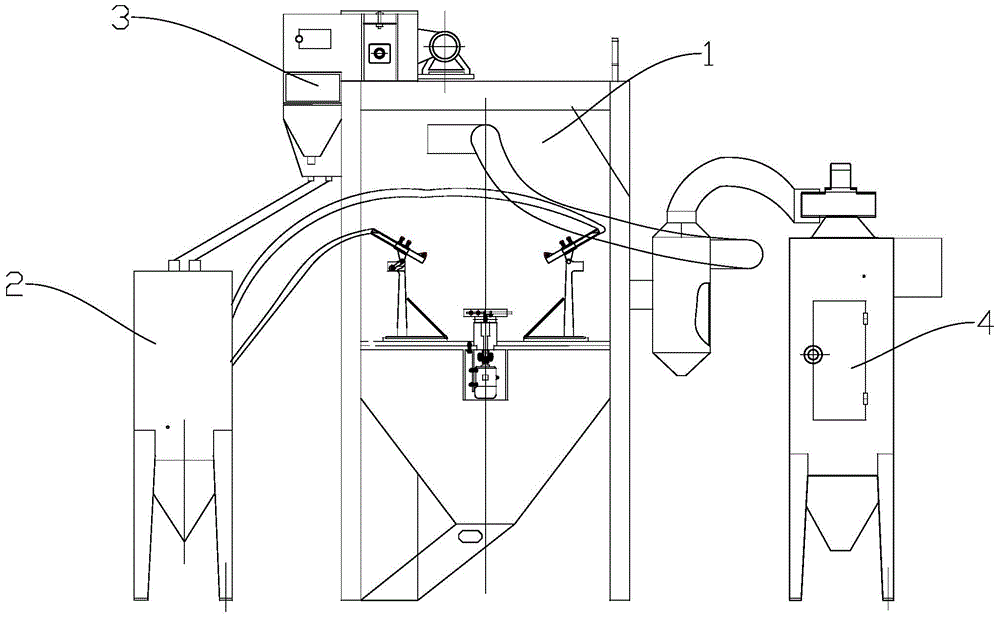
[0025] A test device for blade wear resistance, the device includes a mechanical system and a control system, the mechanical system includes: a shot blasting chamber 1, a shot blaster 2, a shot conveying device 3, and a dust removal device 4; the control system includes an industrial control device computer 5 .

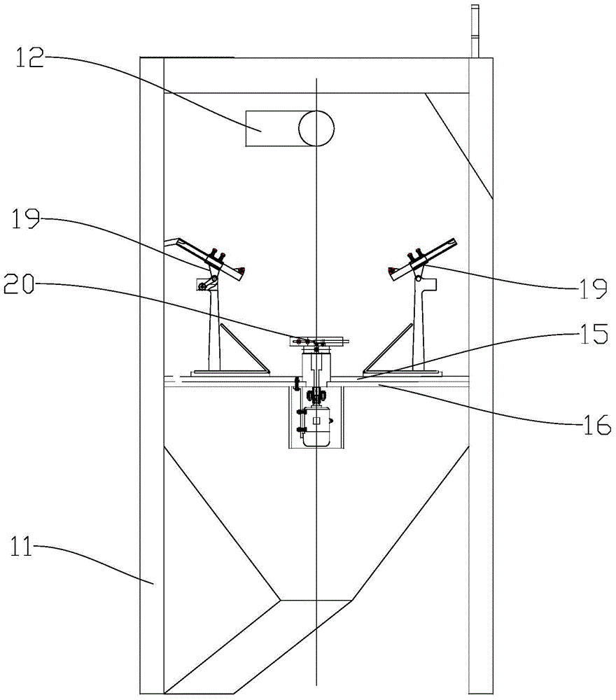
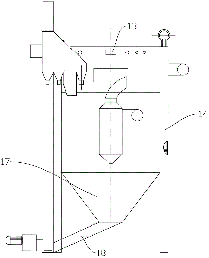
[0026] Such as figure 2 and image 3 As shown, the shot blasting chamber 1 includes: a box body 11, a dust removal port 12, an observation port 13, a hatch 14, a workbench 15, a sand leakage plate 16, a shot recovery device 17, a slide plate 18, a nozzle clamp 19, and a blade clamp 20 .

[0027] The hatch 14 is on the side of the shot blasting chamber 1, and the clamping blades are opened before the test and closed during shot peening. Dust removal port 12 is on the shot blasting chamber 1 top, and is positioned at the adjac...


PUM


Abstract

The invention provides a blade wear resistance test method and device. The device comprises a shot blasting chamber for mounting a blade, a shot blasting device which is located at one side of the shot blasting chamber and is connected with the shot blasting chamber by a pipeline, and a shot material conveying device located above the shot blasting chamber, wherein the shot blasting device comprises nozzles, and the shot blasting chamber comprises a box body; two nozzles are arranged, wherein one nozzle is a sand shot nozzle, and the other nozzle is a pill nozzle; a worktable is arranged at the bottom of the box body and is provided with nozzle clamps and a blade clamp; two groups of nozzle clamps are arranged, wherein one group is a sand blasting clamp, and the other group is a shot blasting clamp; a sand leaking plate is arranged at the lower part of the worktable, and a pill recycling device is arranged at the lower end of the sand leaking plate; and the pill recycling device is connected with the shot material conveying device. According to the device, alternative blasting of two blasting materials, the automatic rotation of a test piece, the adjustment of the blasting speed and time of a shot blasting machine and the like can be finished under the control of an industrial control computer, and a series of test methods for detecting the blade wear resistance are formed by the matching of the processes.

Description

technical field [0001] The invention relates to the technical field of workpiece surface grinding, in particular to a test method and test device for blade wear resistance. Background technique [0002] The working principle of the shot blasting machine is that the shot material enters the shot wheel and the directional sleeve through the shot tube, and after being accelerated by the shot wheel, the shot material flows out from the window of the directional sleeve to the blade, and the shot material is thrown at a high speed under the action of centrifugal force. out and hit the surface of the workpiece to achieve the purpose of cleaning and strengthening the surface of the workpiece. In the above process, the form of friction and wear between the blade and the shot is impact friction and wear. The shot exerts striking force and scouring force on the blade, causing internal cracks on the surface of the blade to expand, and the material is partially shed and lost, resulting i...

Claims


Application Information

Patent Timeline
Patent Type & Authority Applications(China)
IPC IPC(8): G01N3/56
Inventor 王守仁汤以品李亚东高文曹斐乔阳杨学锋
Owner UNIV OF JINAN
Learn More