Routing inspection air vehicle with multiple rotor wings and electric transmission line hanging method thereof
A multi-rotor and aircraft technology, applied in aircraft, overhead line/cable equipment, transportation and packaging, etc., can solve the problems that multi-rotor aircraft cannot accurately mount ground wires, etc., so as to avoid obstacles, improve efficiency, The effect of the precision ground wire mount function
- Summary
- Abstract
- Description
- Claims
- Application Information
AI Technical Summary
Problems solved by technology
Method used
Image
Examples
Embodiment 1
[0070] This embodiment is designed for the disassembly and assembly of the multi-rotor flying device.
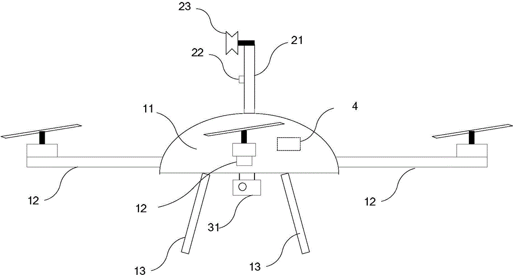
[0071] In this embodiment, the nacelle is an oblate cabin structure, and a plurality of openings are evenly arranged along its circumference, and the plurality of openings correspond to the plurality of rotors one by one; the landing gear can be, but not limited to, fixed on the The bottom of the cabin.
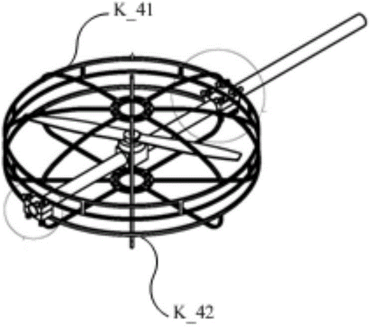
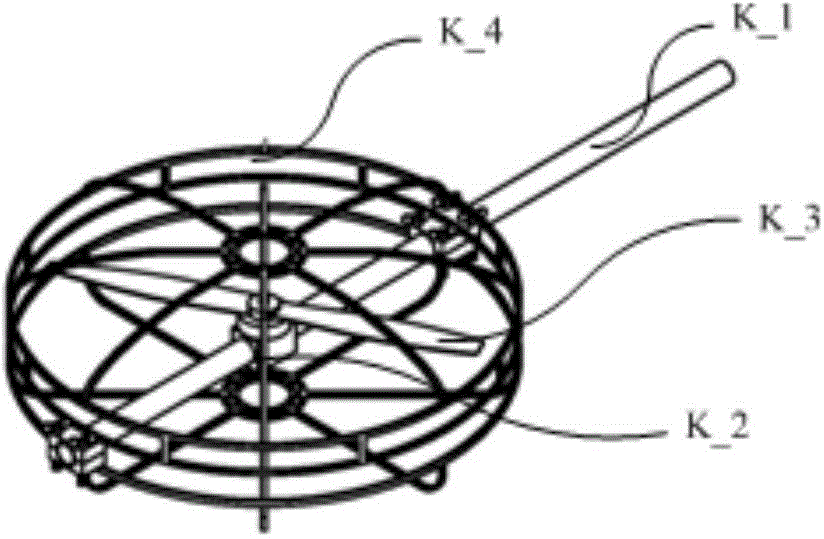
[0072] The rotor in this embodiment specifically includes: a rotor bracket, a brushless motor, a propeller and an anti-collision cover. Wherein, one end of the rotor bracket is plugged and fixed in the corresponding opening; the brushless motor, the propeller and the anti-collision cover are installed on the rotor bracket; Driven by the brush motor to rotate and generate lift; the anti-collision cover is arranged on the outside of the propeller.
[0073] In this embodiment, each rotor and the nacelle are assembled and disassembled through the plug connection between the r...
Embodiment 2
[0080] This embodiment is aimed at the disassembly and assembly design of the falling line traveling device.
[0081] The falling line walking device of this embodiment adopts the structure shown in Figure 3 (a)~(d), including: fixed support L_1, movable support L_2, moving wheel L_3, drive motor L_4, wheel support L_5, support wheel L_6, Guide fence L_7, auxiliary guide fence L_8 and guide camera L_9.
[0082] The bottom end of the fixed bracket L_1 is fixed on the top of the nacelle (not shown in Fig. 3(a)-(d)), and the top end of the fixed bracket L_1 is fixedly connected with the bottom end of the movable bracket L_2.
[0083] The moving wheel L_3, the driving motor L_4, the wheel support L_5, the support wheel L_6, the guide fence L_7 and the auxiliary guide fence L_8 are installed on the top of the movable support L_2. The driving motor L_4 is connected to the wheel shaft of the moving wheel L_3; the wheel bracket L_5 is vertically fixed on the top of the movable bracke...
Embodiment 3
[0090] This embodiment is designed for the disassembly and assembly of the inspection device.
[0091] The inspection device of this embodiment includes: a base, a pan-tilt, and an inspection camera. The base is fixedly connected to the bottom of the nacelle; the pan-tilt is fixed on the side of the base facing away from the nacelle, and the inspection camera is installed on the pan-tilt; Describe the shooting direction of the inspection camera.
[0092] In this embodiment, the fixed connection between the base and the bottom of the nacelle can be realized by bolts. For example, the bottom of the nacelle is provided with at least one downward lug, and the side of the base facing the nacelle is provided with at least one upward lug; The upper lugs match the upward lugs and are connected securely with bolts. That is, the base and the nacelle are disassembled and assembled through the bolt connection between these downward lugs and upward lugs. It should be noted that the lugs...
PUM
 Abstract
Description
Claims
Application Information
 - R&D
- Intellectual Property
- Life Sciences
- Materials
- Tech Scout
- Unparalleled Data Quality
- Higher Quality Content
- 60% Fewer Hallucinations
Browse by: Latest US Patents, China's latest patents, Technical Efficacy Thesaurus, Application Domain, Technology Topic, Popular Technical Reports.
© 2025 PatSnap. All rights reserved.Legal|Privacy policy|Modern Slavery Act Transparency Statement|Sitemap|About US| Contact US: help@patsnap.com


