Vacuum stirrer

A vacuum mixer and vacuum valve technology, applied in cement mixing devices, clay preparation devices, chemical instruments and methods, etc., can solve problems affecting the mechanical strength and performance of plaster molds, low service life of plaster molds, and low production efficiency. Achieve the effects of reducing labor intensity of workers, balancing water absorption and improving service life

Inactive Publication Date: 2015-02-25
李金盛
View PDF6 Cites 3 Cited by
  • Summary
  • Abstract
  • Description
  • Claims
  • Application Information

AI Technical Summary

Problems solved by technology

[0002] Plaster mold is an auxiliary tool widely used in plastic molding in the daily ceramic industry. When making plaster molds, gypsum and water are generally put into the mixing drum according to a certain ratio, and a single motor is used to drive the stirring paddle to stir in the mixing drum to achieve To achieve uniformity, because there are a lot of air bubbles in the gypsum slurry, pinholes appear when the gypsum mold is formed, and the density is low, which seriously affects the mechanical strength and performance of the gypsum mold. The service life of the gypsum mold is low, and the water absorption rate is not equal. The green body made is easy to dry and crack, and the yield decreases
[0003] Because the gypsum will coagulate in a short period of time after adding water to make a slurry, people have made a lot of improvements in continuous exploration, especially the emergence of vacuum mixers, which are suitable for the special needs of gypsum mixing, but the traditional vacuum mixers are still Using a single motor and a single mixing drum to work, workers have to manually operate the stirring shaft up and down when operating the mixer, which is labor-intensive and low in production efficiency.

Method used


Image

  • Vacuum stirrer

Examples


Embodiment Construction

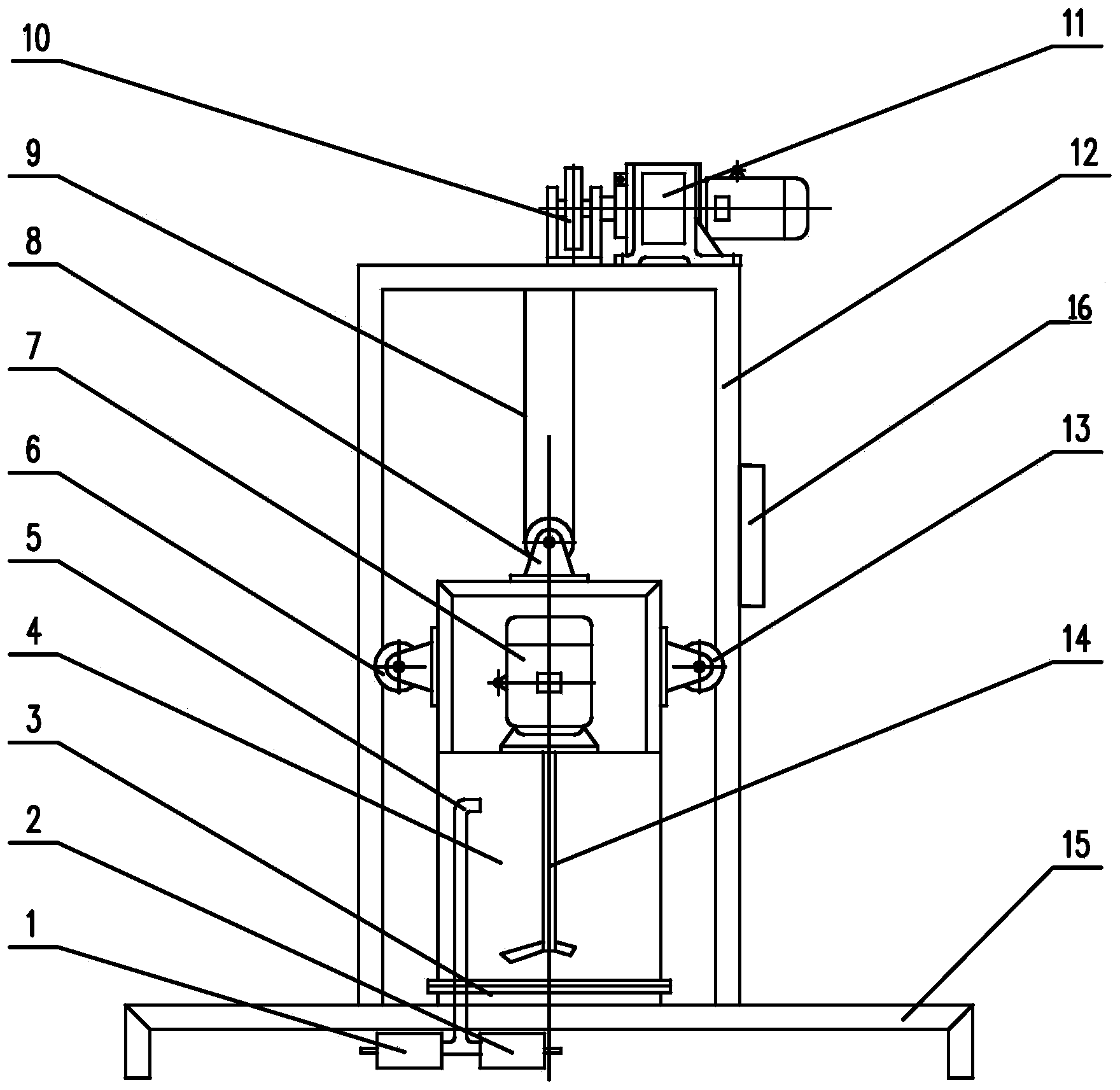
[0019] Such as figure 1 Shown, a kind of vacuum mixer comprises support 15, door-shaped support 12, lower bell jar 3, upper bell jar 4, roll wheel 10, roll wheel motor 11, air pipe 5, wherein, described door-shaped support 12 and described Described lower bell jar 4 is fixedly installed on the support 15, and described lower bell jar 4 is positioned at the internal space of door-shaped support 12, and in the two column inner sides of door-shaped support 12, each is provided with a vertical to base 15. Sliding guide groove (not shown in the figure); Described reel 10 is electrically connected with reel motor 11, and is all positioned on the crossbeam of gate-shaped support 12; Described upper bell jar 4 is positioned at described lower bell jar 3 above, And it is closed with the bell jar 3 by a sealing strip seal, and a stirring motor 7 is installed above the inside of the upper bell jar 4, and the stirring motor 7 is connected with a stirring shaft 14, and the left and right s...


PUM


Abstract

The invention discloses a vacuum stirrer and belongs to the technical field of domestic ceramic mechanical equipment. The vacuum stirrer comprises a machine base, an n-shaped bracket, a lower bell jar, an upper bell jar, a coiling wheel, a coiling wheel motor and an air pipe, wherein the n-shaped bracket and the lower bell jar are fixedly mounted on the machine base; sliding guide slots are formed in the inner sides of two stand columns of the n-shaped bracket; the coiling wheel is electrically connected with the coiling wheel motor and is arranged on the n-shaped bracket; the upper bell jar and the lower bell jar are covered by sealing adhesive tapes; a stirring motor is mounted inside the upper bell jar; guide wheels capable of moving up and down along the sliding guide slots are respectively arranged on the left side and the right side of the outer side of the upper bell jar; a pulley is also arranged at the top of the upper bell jar and is connected with the coiling wheel by virtue of a steel wire rope; the air pipe runs through the machine base and the lower bell jar and extends into the upper bell jar; the lower end of the air pipe is arranged under the machine base and is connected with a vacuum valve and an air valve by virtue of a three-way pipe. The vacuum stirrer is capable of stirring gypsum under the vacuum condition, fully removing bubbles in the process of stirring the gypsum and ensuring that the gypsum is uniformly stirred.

Description

technical field [0001] The invention relates to the technical field of daily-use ceramic mechanical equipment, in particular to a vacuum mixer for producing plaster molds. Background technique [0002] Plaster mold is an auxiliary tool widely used in plastic molding in the daily ceramic industry. When making plaster molds, gypsum and water are generally put into the mixing drum according to a certain ratio, and a single motor is used to drive the stirring paddle to stir in the mixing drum to achieve To achieve uniformity, because there are a lot of air bubbles in the gypsum slurry, pinholes appear when the gypsum mold is formed, and the density is low, which seriously affects the mechanical strength and performance of the gypsum mold. The service life of the gypsum mold is low, and the water absorption rate is not equal. The green body made is easy to dry and crack, and the yield decreases. [0003] Because the gypsum will coagulate in a short period of time after adding wa...

Claims


Application Information

Patent Timeline
IPC IPC(8): B28C5/46
CPCB28C5/464
Inventor 李金盛
Owner 李金盛
Why Eureka
Try Eureka