
Pin roller type one-way overrunning clutch device for motorcycle

A technology of one-way overrunning and clutch devices, applied in one-way clutches, clutches, mechanical equipment, etc., can solve problems affecting the reliability and service life of overrunning clutches, affect the performance of overrunning clutches, increase the weight of overrunning clutches, etc., and achieve the goal of connecting Strong and reliable, good reed positioning, easy processing and assembly

Inactive Publication Date: 2015-02-25
CHONGQING CONGREN ELECTROMECHANICAL
View PDF6 Cites 1 Cited by
  • Summary
  • Abstract
  • Description
  • Claims
  • Application Information

AI Technical Summary

Problems solved by technology

[0004] 1. Since the compression spring needs to be additionally processed with a chute for installation, on the one hand, it is difficult to process the installation chute of the compression spring, which will increase the production cost; Fracture, thus affecting the reliability and service life of the overrunning clutch
[0005] 2. The shield is generally fixed to the body by screws. Not only is it inconvenient to disassemble, but also the tightness of the joint between the shield and the body is poor, and the shield is easy to loosen and produce abnormal noise.
[0006] 3. Although the roller is axially limited by the shield and the baffle, there is a gap between the roller, the shield and the baffle, so that the roller will inevitably be skewed when moving in the wedge-shaped positioning groove, which is also easy to Causes stagnation, thereby affecting the performance of the overrunning clutch; the rollers are usually solid cylinders, not only the material cost is high, but also the weight of the overrunning clutch will be increased when the number of rollers is large

Method used


Image

  • Pin roller type one-way overrunning clutch device for motorcycle
  • Pin roller type one-way overrunning clutch device for motorcycle
  • Pin roller type one-way overrunning clutch device for motorcycle

Examples


Embodiment Construction

[0028] Below in conjunction with accompanying drawing and embodiment the present invention will be further described:

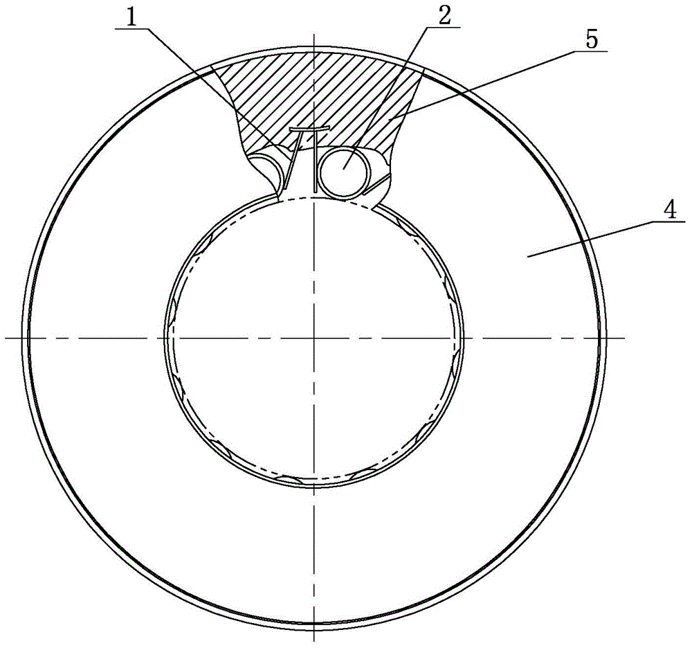
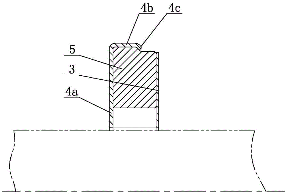
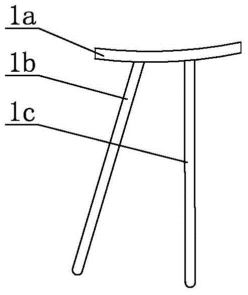
[0029] Such as figure 1 , figure 2 , Figure 4 As shown, the present invention is made of components such as integrated reed 1, roller 2, baffle plate 3, shield 4 and body 5. Wherein, the main body 5 is a ring structure, the peripheral side of the main body 5 is a stepped structure, and the transition between the large section and the small section of the main body 5 peripheral side is through a middle cone section. A shield 4 is provided on one side of the body 5, and a baffle 3 is provided on the other side. The shield 4 is a stamped steel part, consisting of an end 4a, a ring 4b and a bent portion 4c. The end 4a of the shield 4 is in close contact with the end face of the body 5, and the ring 4b of the shield 4 holds the body 5 weeks of extensive covering of the sides. The bending part 4c of the shield 4 is formed by flanging the free end of the ring...


PUM


Abstract

The invention discloses a pin roller type one-way overrunning clutch device for a motorcycle. The pin roller type one-way overrunning clutch device comprises a body (5), a protective cover (4), a baffle (3) and pin rollers (2). The pin rollers (2) are hollow cylinders. Annular grooves (2a) are formed in the middle portions of the pin rollers (2) in a rolling mode. An integrally-formed protruding edge (5a) in a wedge-shaped locating groove is embedded in the corresponding annular groove (2a). An integrated spring leaf (1) is arranged between every two adjacent pin rollers (2) on the circumference and is shaped like a Greek letter phi. According to the pin roller type one-way overrunning clutch device, the pin rollers are driven through the integrated spring leaves, synchronization of movement of the pin rollers can be guaranteed, the performance reliability of an overrunning clutch can be improved, and the service life of the overrunning clutch is longer; meanwhile, the protective cover is of an edge coating installation structure, the protective cover and the body are tightly connected, firmness is good, and the phenomenon of looseness or falling is avoided.

Description

technical field [0001] The invention relates to a one-way device, in particular to a roller type one-way overrunning clutch device for motorcycles. Background technique [0002] The overrunning clutch is a basic component that appears with the development of mechatronics products. It is an important component used for power transmission and separation between the prime mover and the working machine or between the driving shaft and the driven shaft inside the machine. The main functions of the overrunning clutch are: overrunning or transmitting torque, precise positioning, and preventing reverse rotation. [0003] Existing motorcycle overrunning clutch is generally made of body, shield, baffle plate, roller and stage clip. The rollers are installed in the wedge-shaped locating grooves provided on the inner wall of the body, and stage clips are also arranged in the wedge-shaped locating grooves, one stage clip corresponds to one roller, and the stage clips drive the rollers t...

Claims


Application Information

Patent Timeline
Patent Type & Authority Applications(China)
IPC IPC(8): F16D41/064
Inventor 李从仁
Owner CHONGQING CONGREN ELECTROMECHANICAL
Learn More