
Leaf spring type constant pressure valve

A technology of constant pressure valve and shrapnel, which is applied in the direction of safety valve, balance valve, valve device, etc., can solve the problems of unstable pressure in the oil delivery line, abnormal engine fuel, harsh vibration and noise of the valve, etc., and achieve stable delivery, durability Improves corrosion resistance and prolongs service life

Inactive Publication Date: 2015-02-25
温州仁谦汽车油泵有限公司
View PDF7 Cites 2 Cited by
  • Summary
  • Abstract
  • Description
  • Claims
  • Application Information

AI Technical Summary

Problems solved by technology

However, most of the existing constant pressure valves in the market are spring-type constant-pressure valves, and when the volume of the spring-type constant-pressure valve is too small, there is not enough space for the spring to expand, and the slope curve of the constant-pressure valve will become steeper, which will make the output The pressure in the oil circuit is unstable, which makes the fuel supplied to the engine abnormal and easily damages the engine, and the oil in the oil supply circuit of the oil pump is not a continuous fluid, but composed of sections of oil, so that the oil The formed fluid has a certain vibration frequency, so that the oil with vibration frequency will be transmitted to the spring when it passes through the constant pressure valve, and the spring itself has a large damping change. When the frequency of the oil is the same as that of the spring type constant pressure valve When the frequency of the inner spring is the same, the two will resonate, which doubles the overall vibration of the valve, thus causing the valve to produce harsh vibration noise

Method used


Image

  • Leaf spring type constant pressure valve

Examples


Embodiment Construction

[0014] In order to make the content of the present invention more clear, the present invention will be further described in detail below in conjunction with the examples. It should be understood that the specific embodiments described here are only used to explain the present invention, not to limit the present invention.

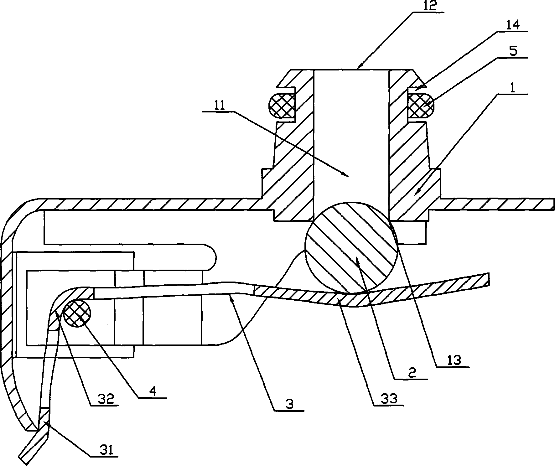
[0015] Such as figure 1 As shown, a shrapnel type constant pressure valve according to the embodiment of the present invention includes a valve seat 1 and a steel ball 2. A constant pressure chamber 11 is provided in the valve seat 1, and the two ends of the constant pressure chamber 11 are oil inlets 12 respectively. And the oil outlet 13, the steel ball 2 is set at the oil outlet 13 of the valve seat 1, further, a curved shrapnel 3 is installed on the valve seat 1, the shrapnel 3 is formed by the connecting part 31, the supporting part 32 and the abutment The pressing part 33 is composed of the connecting part 31 of the elastic piece 3 fixedly connected ...


PUM


Abstract

The invention discloses a leaf spring type constant pressure valve which comprises a valve base and a steel ball. A constant pressure cavity is formed inside the valve base. The two ends of the constant pressure cavity are provided with an oil inlet and an oil outlet respectively. The steel ball is arranged at the position of an oil outlet of the valve base. A bent leaf spring is installed on the valve base. The leaf spring is composed of a connecting portion, a supporting portion and an abutting pressing portion. The connecting portion of the leaf spring is fixedly connected to the valve base. The supporting portion of the leaf spring is supported on a pin shaft installed on the valve base to form a supporting point of the leaf spring. The abutting pressing portion of the leaf spring is pressed on the steel ball in an abutting mode so that the steel ball and the oil outlet of the valve base can form a sealing state. The leaf spring type constant pressure valve is simple and reasonable in structure, interference caused by the insufficient extending space will not be caused when the size of the valve is decreased, the oil conveying stability can be well kept, the service life of an engine is prolonged, and noise generated by the valve can be greatly reduced.

Description

technical field [0001] The invention relates to the technical field of valves, in particular to a shrapnel type constant pressure valve. Background technique [0002] The constant pressure valve plays an important role in the automotive fuel injection system. When the oil pump in the fuel tank pumps oil out to the engine, a certain pressure is required in the oil delivery line to ensure that the oil injected into the engine is in an ideal mist shape, so that The oil is fully burned, and in order to maintain the required pressure in the oil delivery circuit, a constant pressure valve needs to be added to the oil circuit system. When the constant pressure valve works in the oil circuit, the opening pressure of the constant pressure valve will increase with the increase of the flow rate. As the flow rate increases, the curve generated by the pressure change of the constant pressure valve is called the slope curve of the constant pressure valve. Undoubtedly, the gentler the slo...

Claims


Application Information

Patent Timeline
Patent Type & Authority Applications(China)
IPC IPC(8): F16K17/06
CPCF16K17/06
Inventor 池长风
Owner 温州仁谦汽车油泵有限公司
Learn More