Novel ultrasonic humidifier

An ultrasonic and humidifier technology, which is applied in the field of new ultrasonic humidifiers, can solve the problems of not being able to automatically follow the resonant frequency of the atomizing sheet, damage the life of the humidifier, and complex circuit structure, so as to avoid dehydration oscillation, dry burning, and safety performance Good results

Inactive Publication Date: 2015-02-25
潘浩斌
View PDF8 Cites 15 Cited by
  • Summary
  • Abstract
  • Description
  • Claims
  • Application Information

AI Technical Summary

Problems solved by technology

[0003] The basic structure of a traditional ultrasonic humidifier is generally composed of a power supply circuit, a control circuit, an oscillating circuit, a fan and a transducer (piezoelectric ceramic sheet), and the control circuit includes a water shortage detection, water shortage indication and fog volume adjustment circuit. Water detection is generally a dry reed switch with a floating magnetic ring detection method, or a water surface probe detection method, and its circuit structure is relatively complicated
The oscillating circuit of traditional ultrasonic humidifiers generally adopts self-excited oscillation. As we all know, self-excited oscillation is harmful to the components in the circuit and will damage the life of the humidifier, and the frequency of the ultrasonic signal sent cannot automatically follow the resonant frequency of the atomizer.
Humidifier oscillating circuits are mostly driven by power tubes, which generate more heat and consume more power

Method used


Image

  • Novel ultrasonic humidifier
  • Novel ultrasonic humidifier

Examples


Embodiment Construction

[0025] It should be understood that the specific embodiments described herein are only used to explain the present invention, but not to limit the present invention.

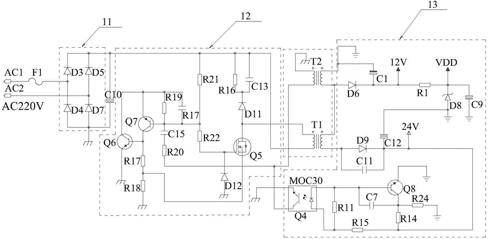
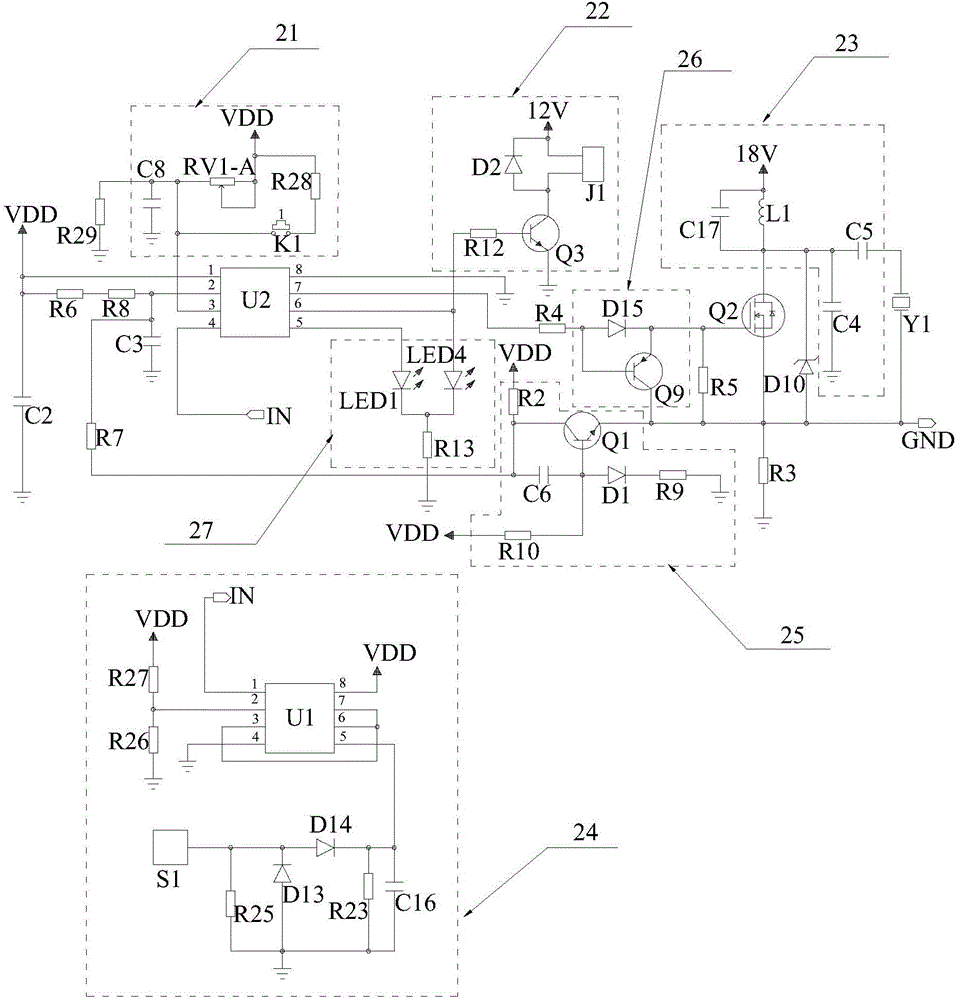
[0026] refer to figure 1 and figure 2 , proposes an embodiment of the novel ultrasonic humidifier of the present invention, the novel ultrasonic humidifier includes a power supply circuit, an ultrasonic oscillation circuit connected to the power output end of the power supply circuit, a pneumatic device 22 connected to the output end of the ultrasonic oscillation circuit, an indicator Circuit 27, atomizing device and water shortage detection circuit 24. The atomizing device is an atomizing sheet Y1, and the pneumatic device 22 includes a fan J1 and a fan drive circuit 26, which atomizes the water into ultrafine particles of one to five microns through the resonance of the atomizing sheet, and diffuses the water mist into the air through the pneumatic device 22. In the air, so as to achieve the purpose of even...


PUM


Abstract

The invention discloses a novel ultrasonic humidifier which comprises a power circuit, an ultrasonic oscillating circuit, a pneumatic device connected with the output end of the ultrasonic oscillating circuit, an atomizing device and a water shortage detection circuit. The ultrasonic oscillating circuit comprises a main control chip, a mist amount regulating circuit, an automatic frequency regulating circuit, a power amplification circuit and a resonance circuit, wherein the mist amount regulating circuit and the automatic frequency regulating circuit are connected with the two input ends of the main control chip respectively, the power amplification circuit is connected with one output end of the main control chip, the resonance circuit is connected with the power amplification circuit and connected with the atomizing device, and the other output end of the main control chip is connected with the pneumatic device. The water shortage detection circuit detects ultrasonic waves conducted by water through an ultrasonic water level detection induction probe, ultrasonic signals enter a comparator through a peak detection circuit, the compared high-low electrical levels are transmitted to a pin 4 of the main control chip, the main control chip judges whether the water level is lower than the ultrasonic water level detection induction probe or not according to the electrical levels received by the pin 4, and thus the purpose of preventing dry burning is achieved.

Description

technical field [0001] The invention relates to a humidifier, in particular to a novel ultrasonic humidifier with compact circuit structure. Background technique [0002] In order to add humidity to dry indoors, people often use humidifiers to add moisture to the air. As a relatively mature humidification product, ultrasonic humidifier has won the favor of consumers. The working principle of ultrasonic humidifier is to use the principle of ultrasonic high-frequency oscillation to atomize water into ultra-fine particles of one to five microns. The water mist is diffused into the air, so as to achieve the purpose of evenly humidifying the air, moisturizing the air and accompanied by abundant negative oxygen ions, achieving uniform humidity, freshening the air, improving health, changing the dryness and heat of heating in winter, and creating a comfortable home environment. . [0003] The basic structure of traditional ultrasonic humidifier is generally composed of power supp...

Claims


Application Information

Patent Timeline
Patent Type & Authority Applications(China)
IPC IPC(8): F24F6/12F24F11/00
CPCF24F6/12F24F11/0008F24F11/30F24F2110/00Y02B30/70
Inventor 潘浩斌
Owner 潘浩斌
Why Eureka
Try Eureka