An Adaptive Software UML Modeling and Its Formal Verification Method

A formal verification and self-adaptive technology, applied in software testing/debugging, program control devices, execution paradigms, etc., can solve the problems of immature research, difficulty in understanding and mastering, poor readability, etc., and achieve a high degree of visualization and improve Improvement of development efficiency and reliability

Active Publication Date: 2018-06-05
PLA UNIV OF SCI & TECH
View PDF2 Cites 0 Cited by
  • Summary
  • Abstract
  • Description
  • Claims
  • Application Information

AI Technical Summary

Problems solved by technology

Existing software requirements analysis and modeling methods (such as UML) lack facilities in the field of adaptive software, and cannot be directly used for modeling adaptive software, and it lacks a formal analysis and verification mechanism for the model, which can be formally verified directly Very difficult; existing formal methods (such as timed automata models) are too abstract, difficult to understand and master, and difficult to directly apply to industrial practice
Therefore, in most of the current research work, there is a "gap" between the visual modeling of adaptive software and formal modeling, which leads to visual methods that are intuitive but lack a strict analysis mechanism, which is unconvincing; The method definition is strict, but the readability is poor, and it is difficult for software engineers to understand and master
Although a few scholars (such as Andres J.Ramirez and Betty H.C.Cheng of Michigan State University) have tried to combine visual modeling methods and formal modeling methods for modeling and formal verification of adaptive software, but this aspect The research is immature and lacks consideration of factors such as model conversion algorithms and adaptive characteristics

Method used


Image

  • An Adaptive Software UML Modeling and Its Formal Verification Method
  • An Adaptive Software UML Modeling and Its Formal Verification Method
  • An Adaptive Software UML Modeling and Its Formal Verification Method

Examples


Embodiment

[0062] Below in conjunction with embodiment the present invention is described in further detail:

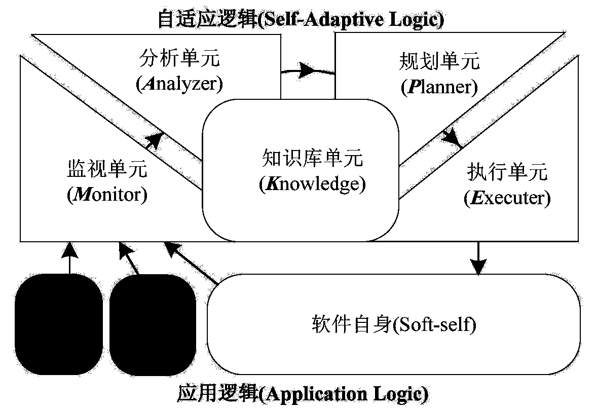
[0063] Taking a simplified Web-based client / server system as an example, the implementation steps of the method of the present invention are set forth; ZNN.com is a Web-based client / server system, and its client is connected to the server pool Server Pool, and system maintenance personnel can Manually add or remove servers according to system load and user needs, and the client sends user needs to the server in real time, providing text (Textual) or multimedia (Multimedia) web page services. Due to the dynamic changes in client user visits, manually adjusting the size of the server pool can no longer adapt to frequent changes in the environment. Therefore, the software adaptive logic is constructed on the original software system to endow the system with adaptive capabilities;

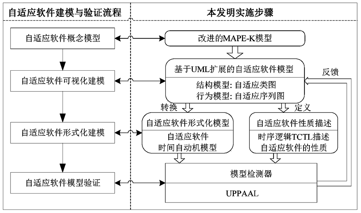
[0064] Step 1. Guided by the improved MAPE-K software self-adaptive conceptual model, conduct d...


PUM


Abstract

The invention discloses a self-adaptive software UML modeling and a formal verification method thereof, which are mainly used to deal with the problems of modeling and verification of self-adaptive software, and the specific steps include: (1) establishing a conceptual model of self-adaptive software; (2) By extending UML to introduce new stereotypes, tagged values ​​and constraints, establish a visual model of adaptive software, including adaptive software structural model adaptive class diagram and behavioral model adaptive sequence diagram; (3) design model conversion algorithm will The behavior model of the adaptive software is converted into a timed automaton network, and the formal model of the adaptive software is established; (4) The TCTL temporal logic specification describing the nature of the adaptive software is given, and the model checking tool UPPAAL is used to verify the validity of the adaptive software model Reliability, and further optimize the UML model of the adaptive software according to the feedback results. The invention can effectively reduce the complexity of software self-adaptive modeling and verification, and improve the modeling efficiency and model reliability of software self-adaptive.

Description

technical field [0001] The invention belongs to the technical fields of new software methods and software modeling and verification, in particular to self-adaptive software UML modeling and formal verification methods. Background technique [0002] Adaptive software / software adaptive technology is a new software design paradigm. This type of software can effectively reduce software maintenance pressure, enhance its own fault tolerance and ability to respond to changes, and it endows software with an automatic ability to respond to changes in the environment and user needs. Adaptability, which enables the software to collect software context information in real time during operation, and adjust its parameters, structure or behavior when necessary according to the preset strategy, so as to eliminate or mitigate the changes caused by the changes in time. Adverse effects of the software to ensure continuous and uninterrupted service provision. Due to the dynamic and changeable ...

Claims


Application Information

Patent Timeline
Patent Type & Authority Patents(China)
IPC IPC(8): G06F9/448G06F11/36
Inventor 邢建春韩德帅杨启亮王平王洪达张学伟
Owner PLA UNIV OF SCI & TECH
Why Eureka
Try Eureka