Mobile terminal broadband antenna with adjustable capacitors for impedance matching
A technology for mobile terminals and impedance matching, which is applied in the connection of antennas, antenna grounding switches, devices that enable antennas to work in different bands at the same time, and can solve the problems that adjustable capacitor antennas cannot be widely used in high-efficiency and broadband applications. Achieve the effects of effective expansion of working bandwidth, easy production, and convenient miniaturization design
- Summary
- Abstract
- Description
- Claims
- Application Information
AI Technical Summary
Problems solved by technology
Method used
Image

Examples
Embodiment 1
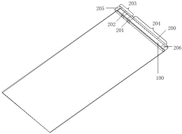
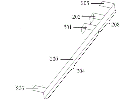
[0028] Such as figure 1 As shown, the mobile terminal broadband antenna provided by the present invention adopts adjustable capacitance for impedance matching, including a bracket 100, an antenna body 200 fixed on the bracket 100, and an antenna matching circuit 300 ( figure 1 not shown), the antenna body 200 is electrically connected to the antenna matching circuit 300 . Such as figure 2 As shown, the antenna body 200 is an elongated structure with a feeding point 201 and a grounding point 202 on the elongated structure. The elongated structure is divided into a long arm 204 and a short arm by the feeding point 201 203 , the grounding point 202 is located on the short arm 203 .
[0029] The width of the long arm 204 and the short arm 203 is the maximum width of the support 100, and the length of the elongated structure is the maximum length of the support 100, that is, the antenna body is spread as much as possible on the support, which can maximize the maximum width of a ...
Embodiment 2
[0034] In this embodiment, except that the antenna matching circuit is different from that in Embodiment 1, other parts are the same as in Embodiment 1. The antenna matching circuit 300 in this embodiment is as Figure 4 As shown, the first inductance 303 is added on the basis of the antenna matching circuit provided in the first embodiment. Wherein, one end of the first inductor 303 is grounded, and the other end is connected to the second end of the first adjustable capacitor 301 . In this embodiment, the second adjustable capacitor 302 and the first inductor 303 constitute an LC resonant circuit. The resonant wave formed by the LC resonant circuit will form a double resonant wave together with the existing low-frequency resonant wave in the 698-960MHz frequency band, which broadens the frequency bandwidth of a single state.
Embodiment 3
[0036] In this embodiment, except that the antenna matching circuit is different from that in Embodiment 1, other parts are the same as in Embodiment 1. The antenna matching circuit 300 in this embodiment is as Figure 5As shown, the second inductor 305 and the third adjustable capacitor 304 are added on the basis of the antenna matching circuit provided in the second embodiment. Wherein, one end of the second inductor 305 is grounded, and the other end is connected to the ground point 202 of the antenna body 200 ; one end of the third adjustable capacitor 304 is grounded, and the other end is connected to the first end of the first adjustable capacitor 301 . The second inductor 305 in this embodiment can effectively improve the return loss of the antenna in the low frequency band, and the third adjustable capacitor 304 is used to improve the performance of the antenna in the high frequency band. When the capacitance value of the third adjustable capacitor is adjusted, the re...
PUM
 Abstract
Description
Claims
Application Information
 - R&D
- Intellectual Property
- Life Sciences
- Materials
- Tech Scout
- Unparalleled Data Quality
- Higher Quality Content
- 60% Fewer Hallucinations
Browse by: Latest US Patents, China's latest patents, Technical Efficacy Thesaurus, Application Domain, Technology Topic, Popular Technical Reports.
© 2025 PatSnap. All rights reserved.Legal|Privacy policy|Modern Slavery Act Transparency Statement|Sitemap|About US| Contact US: help@patsnap.com