
Braking energy recycling system, braking energy recycling method and crane

A braking energy recovery and braking energy technology, which is applied in control devices, auxiliary drive devices, transportation and packaging, etc., can solve the problems of poor fuel economy of the whole machine, insufficient climbing ability, and difficulty in starting, so as to improve fuel economy performance, to achieve the effect of energy utilization

Inactive Publication Date: 2015-03-04
XUZHOU HEAVY MASCH CO LTD
View PDF5 Cites 5 Cited by
  • Summary
  • Abstract
  • Description
  • Claims
  • Application Information

AI Technical Summary

Problems solved by technology

[0003] During the starting and climbing process of crane products, due to the heavy weight of the whole machine, the engine speed is generally low, usually in the non-optimal fuel economy zone of the engine, which will inevitably lead to poor fuel economy of the whole machine, difficulty in starting, and insufficient climbing ability
[0004] During the braking process of crane products, mechanical friction brakes are used. Through the mutual extrusion and friction of braking parts and moving parts, heat is generated and consumed in the air; Higher, resulting in huge waste of energy during frequent braking
[0005] Moreover, the frequent start and stop of the crane makes the engine often in the low-efficiency zone, and frequent braking and starting also consume a lot of energy. However, the existing crane products fail to recover and utilize the energy during the braking process. The improvement of power performance is basically achieved by matching high-power engines, and the fuel economy of the whole machine is low during driving.

Method used


Image

  • Braking energy recycling system, braking energy recycling method and crane
  • Braking energy recycling system, braking energy recycling method and crane
  • Braking energy recycling system, braking energy recycling method and crane

Examples


Embodiment Construction

[0039] The following will clearly and completely describe the technical solutions in the embodiments of the present invention with reference to the drawings in the embodiments of the present invention. Apparently, the described embodiments are only some of the embodiments of the present invention, not all of them. Based on the embodiments of the present invention, all other embodiments obtained by persons of ordinary skill in the art without creative efforts fall within the protection scope of the present invention.

[0040] First, the technical terms used in the present invention are explained.

[0041] Crane: The chassis has the same function as the heavy truck. It uses tires to drive on the road, and uses hooks or other pick-up devices to hang heavy objects when getting on the truck. It is a machine that performs cyclical operations such as lifting and moving in space.

[0042] Hydraulic pump / motor: The hydraulic pump / motor is an important component to realize the conversi...


PUM


Abstract

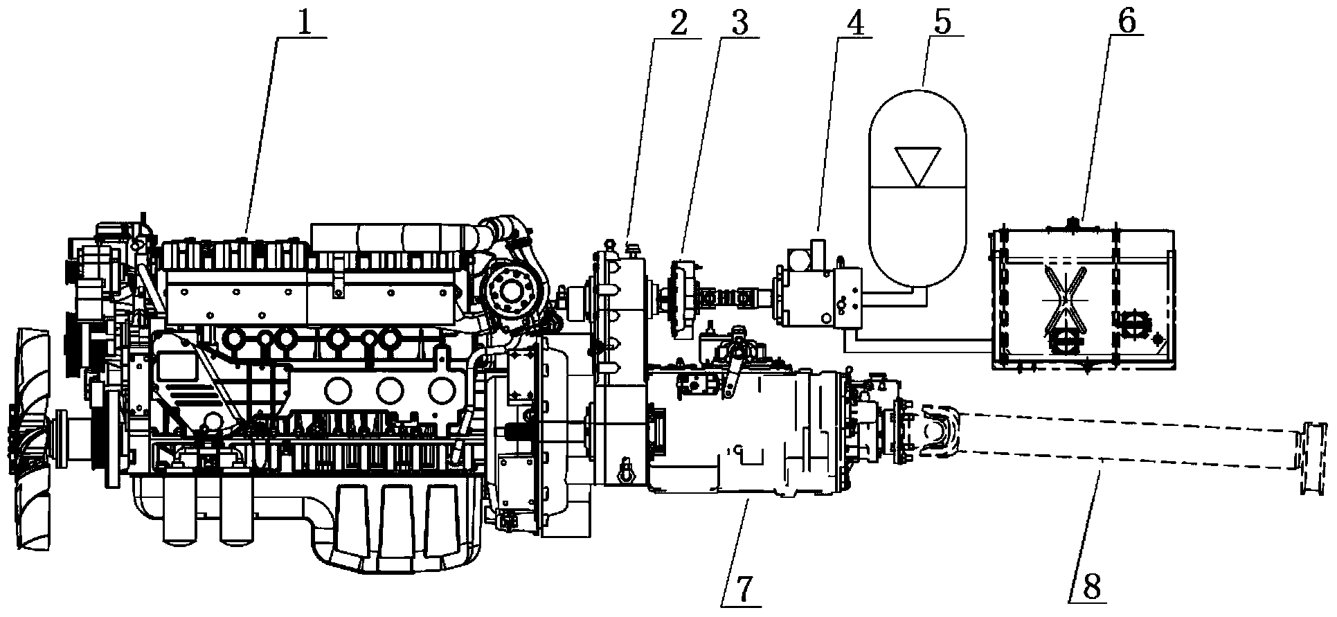
The invention relates to a braking energy recycling system, a braking energy recycling method and a crane, wherein the braking energy recycling system comprises an engine, a power coupler connected with the engine, and a clutch and a gearbox in parallel connection with the power coupler. The clutch is connected with a hydraulic pump / motor; the hydraulic pump / motor is in parallel connection with an energy accumulator and a hydraulic oil tank; and the gearbox is connected with a transmission mechanism. In the braking process, braking mechanical energy is converted to hydraulic energy by the transmission mechanism, the gearbox, the power coupler, the clutch and the hydraulic pump / motor, and the hydraulic energy is stored in the energy accumulator to realize the braking energy recovery; and in the starting, accelerating and climbing processes, the energy stored in the energy accumulator is converted into the mechanical energy by the hydraulic pump / motor, and the mechanical energy drives the whole vehicle to move through the transmission of the gearbox, thereby satisfying the power requirements and realizing the energy utilization. The system can effectively recycle the energy generated in the braking process and thus improve the whole machine fuel economy and the whole machine power performance and braking performance.

Description

technical field [0001] The invention relates to the field of engineering machinery, in particular to a braking energy recycling system, a recycling method and a crane. Background technique [0002] Crane products have large installed power, heavy vehicle weight, and are widely used. They are often used in urban areas and between cities. During the driving process, there are frequent starting, accelerating, braking, and climbing processes. [0003] During the starting and climbing process of crane products, due to the heavy weight of the whole machine, the engine speed is generally low, and it is usually in the non-optimal fuel economy zone of the engine, which will inevitably lead to poor fuel economy of the whole machine, difficulty in starting, and insufficient climbing ability. [0004] During the braking process of crane products, mechanical friction brakes are used. Through the mutual extrusion and friction of braking parts and moving parts, heat is generated and consum...

Claims


Application Information

Patent Timeline
IPC IPC(8): B60K25/00B60K17/28
Inventor 单增海东权张正得朱磊陈延波王帅
Owner XUZHOU HEAVY MASCH CO LTD
Learn More