Micro spherical type short coherent point diffraction interference measurement system and method

A point diffraction interferometry and measurement system technology, applied in the field of microspherical short coherent point diffraction interferometry systems, can solve the problems affecting measurement accuracy, poor contrast of interference fields, etc., to achieve high measurement accuracy, increase coverage area, avoid multiple the effect of interference

Active Publication Date: 2015-03-04
HARBIN INST OF TECH
View PDF7 Cites 12 Cited by
  • Summary
  • Abstract
  • Description
  • Claims
  • Application Information

AI Technical Summary

Problems solved by technology

[0005] The purpose of the present invention is to solve the problem that the contrast of the interference field is poor in the existing short-coherence phase-shifting point diffr

Method used


Image

  • Micro spherical type short coherent point diffraction interference measurement system and method
  • Micro spherical type short coherent point diffraction interference measurement system and method

Examples


specific Embodiment approach 1

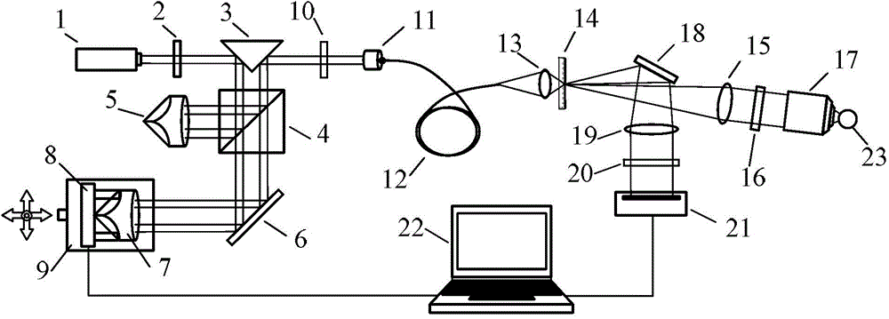
[0030] Specific implementation mode one: the following combination figure 1 Describe this embodiment, the microspherical surface type short coherence point diffraction interferometry system described in this embodiment, it comprises short coherence laser 1, first λ / 2 wave plate 2, right-angle reflector 3, polarization beam splitter prism 4, first angle Axicon prism 5, first plane mirror 6, second corner aconite prism 7, PZT phase shifter 8, delay platform 9, second λ / 2 wave plate 10, fiber coupling mirror 11, single-mode polarization-maintaining fiber 12, converging lens 13 , pinhole mirror 14, first collimator lens 15, λ / 4 wave plate 16, microscope objective lens 17, second plane mirror 18, second collimator lens 19, polarizer 20, area array CCD21 and computer 22,

[0031] The outgoing laser light of the short coherent laser 1 enters the right-angle reflector 3 through the first λ / 2 wave plate 2, and the light incident surface of the right-angle reflector 3 is perpendicular t...

specific Embodiment approach 2

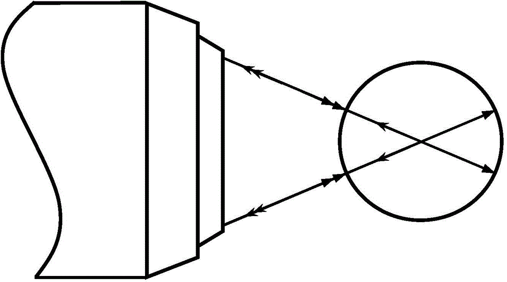
[0039] Specific implementation mode two: the following combination figure 1 Describe this embodiment mode, this embodiment mode will further illustrate embodiment one, described first collimating lens 15, λ / 4 wave plate 16, microscopic objective lens 17 are coaxial with tested microsphere 23;

[0040] The focal point of the first collimator lens 15 coincides with the pinhole of the pinhole mirror 14 .

specific Embodiment approach 3

[0041] Specific implementation mode three: the following combination figure 1 This embodiment will be described. This embodiment will further describe Embodiment 1 or 2. The center of the measured microsphere 23 is located at the center of the light beam emitted by the microscopic objective lens 17 .


PUM

PropertyMeasurementUnit
Diameteraaaaaaaaaa

Abstract

The invention provides a micro spherical type short coherent point diffraction interference measurement system and method and belongs to the micro spherical type detection technical field. The micro spherical type short coherent point diffraction interference measurement system and method aims at solving the problems that the contrast ratio of the interference field of the existing short coherent point diffraction interference measurement method is poor and accordingly the measurement accuracy is affected. The micro spherical type short coherent point diffraction interference measurement system comprises a short coherent laser, a first half lambda wave plate, a rectangular reflecting mirror, a polarization splitting prism, a first pyramid prism, a first plane mirror, a second pyramid prism, a PZT (Piezoelectric Ceramic Transducer) phase shifter, a delay platform, a second half lambda wave plate, an optical fiber coupling mirror, a single-mode polarization-maintaining optical fiber, a convergent lens, a pinhole lens, a first collimating lens, a quarter lambda wave plate, a micro-objective, a second plane mirror, a second collimating lens, a polaroid, an area array CCD (Charge Coupled Device) and a computer. According to the micro spherical type short coherent point diffraction interference measurement method, an optical path structure that the quarter lambda wave plate is combined with the polaroid is adopted to select beams in the interference field and accordingly direct current components in the beams are reduced, the contrast ratio of interference fringes is improved, and the adjustable optimization of the contrast ratio is implemented. The micro spherical type short coherent point diffraction interference measurement system and method is applied to the micro spherical type detection.

Description

technical field [0001] The invention relates to a microspherical short coherence point diffraction interferometry system and a measurement method, belonging to the technical field of microspherical detection. Background technique [0002] As one of the most commonly used components, microspheres are used in many fields such as aerospace, military, industry, and medical treatment. The surface accuracy of microspheres has a crucial impact on their performance. [0003] Although the methods such as atomic force microscope and confocal microscope used in traditional technology to detect microspheres have high longitudinal measurement accuracy, their single measurement range is very small, and they need to cooperate with high-precision mechanical scanning motion devices to realize the overall three-dimensional shape. This method is seriously affected by mechanical motion errors, and has problems such as low detection efficiency, poor lateral resolution, and easy omission of isola...

Claims


Application Information

Patent Timeline
IPC IPC(8): G01B11/24
Inventor 卢丙辉甘雨刘炳国刘国栋陈凤东庄志涛
Owner HARBIN INST OF TECH
Why Eureka
Try Eureka