Radar three-dimensional deformation field reconstruction technology based on general least squares adjustment

A generalized least squares and three-dimensional deformation technology, which is applied in the direction of radio wave reflection/re-radiation, re-radiation, and measurement devices, can solve problems such as inability to meet quantitative analysis, high cost, and deformation patterns revealed by surface deformation characteristics.

Inactive Publication Date: 2015-03-04
HUAIHAI INST OF TECH
View PDF3 Cites 4 Cited by
  • Summary
  • Abstract
  • Description
  • Claims
  • Application Information

AI Technical Summary

Problems solved by technology

However, only one-dimensional deformation can be obtained by using an image pair, because the deformation obtained by differential interference is the result of projecting the deformation in three directions of NEU to the radar line of sight (LOS), so it can only be qualitatively understood based on an image pair The seismic deformation field cannot meet the needs of quantitative analysis, so that the synthetic aperture radar differential interferometry technology cannot be used to explain or understand the surface deformation characteristics and reveal the deformation mode, otherwise it will favor misunderstanding
Compared with synthetic aperture radar differential interferometry, GNSS monitoring results have the advantages of clear quantification, high precision, consistent time scale, and clear dynamic meaning. However, when using discrete GNSS results to solve the spatial distribution of deformation and strain fields, it is necessary to Fitting or interpolation leads to the removal of the high-frequency part of the deformation, that is, the fine features of the deformation are ignored. Although the leveling measurement has high precision, it can only obtain the vertical deformation information and the cost is high

Method used


Image

  • Radar three-dimensional deformation field reconstruction technology based on general least squares adjustment
  • Radar three-dimensional deformation field reconstruction technology based on general least squares adjustment
  • Radar three-dimensional deformation field reconstruction technology based on general least squares adjustment

Examples


Embodiment Construction

[0017] The specific embodiments of the present invention will be further described in detail with reference to the accompanying drawings:

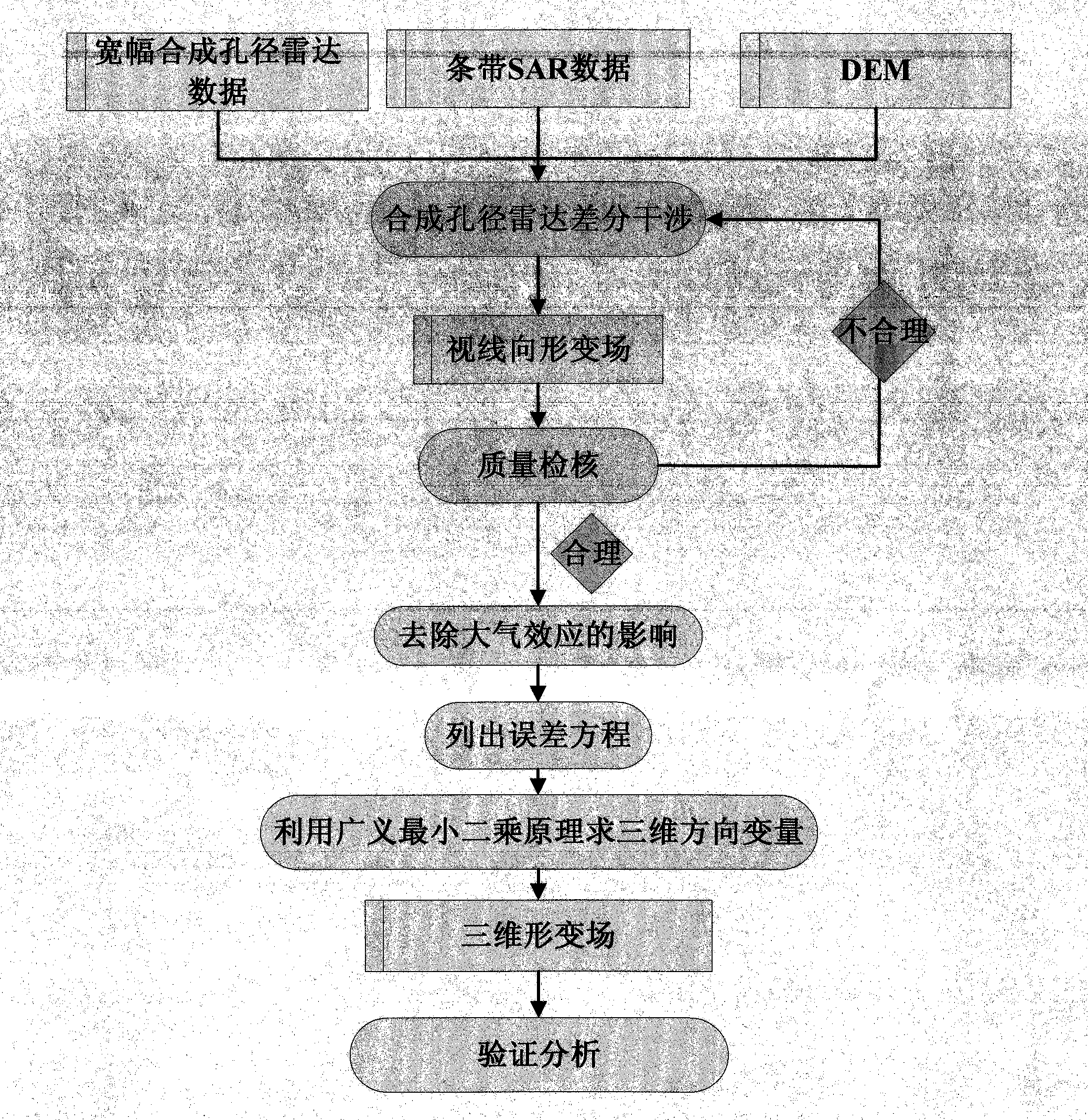
[0018] Such as figure 1 As shown, the radar three-dimensional deformation field reconstruction technology based on generalized least squares adjustment, the technology of using synthetic aperture radar satellites to obtain the line-of-sight deformation field; the technology to remove the influence of atmospheric effects; the error equation of the three-dimensional directional deformation is listed; The principle of least squares solves the three-dimensional directional deformation; the verification analysis technique; the technical steps are as follows:

[0019] Step 1: Use wide-width and striped synthetic aperture radar data to perform differential interferometry with DEM respectively to obtain two modes of line-of-sight deformation fields. The methods involved include registration, resampling and phase unwrapping;

[0020] Step 2: Check whethe...


PUM


Abstract

The invention discloses a radar three-dimensional deformation field reconstruction technology based on general least squares adjustment, which is characterized in that a synthetic aperture radar satellite is used for acquiring a sight line deformation field technology; an atmospheric effect influence technology is removed; an error equation for the three-dimensional direction deformation is listed; a general least squares adjustment principle is used for solving the three-dimensional direction deformation amount; and an analysis technology is verified. The radar three-dimensional deformation field reconstruction technology based on general least squares adjustment has the following advantages that the modern advanced measurement technology and equipment are used, and a station does not need to be built in a monitoring region; the spatial domain in the case of monitoring is maintained to be continuous; three-dimensional distribution situations in the surface deformation space are acquired; and defects of low three-dimensional vector decomposition accuracy in traditional methods such as a pixel offset estimation method, a multi-aperture interference method and an external measurement assisting method can be overcome.

Description

technical field [0001] The present invention mainly relates to three-dimensional deformation field reconstruction technology, in particular to radar three-dimensional deformation field reconstruction technology based on generalized least squares adjustment. Background technique [0002] As an emerging space geodetic technology, InSAR technology can obtain high-precision and high-resolution deformation information without providing ground control points. Compared with other geodetic methods, it has an irreplaceable role. Now it has been successfully applied in coseismic deformation monitoring, ground fissure monitoring, land subsidence monitoring and volcano research, and has achieved breakthrough research results. Research results in earthquakes show that InSAR technology has played a huge role in geodynamics and earthquake research. However, only one-dimensional deformation can be obtained by using an image pair, because the deformation obtained by differential interferenc...

Claims


Application Information

Patent Timeline
Patent Type & Authority Applications(China)
IPC IPC(8): G01S13/90
CPCG01S13/9023
Inventor 蒋廷臣
Owner HUAIHAI INST OF TECH
Why Eureka
Try Eureka