Variable gain amplifier in current mode

A gain amplifier, current mode technology, applied in amplifiers, DC-coupled DC amplifiers, differential amplifiers, etc., can solve problems such as narrowing bandwidth and unfavorable broadband occasions, reducing impact, unlimited bandwidth, and reducing power consumption. Effect

Active Publication Date: 2015-03-04
SOUTHEAST UNIV +1
View PDF7 Cites 6 Cited by
  • Summary
  • Abstract
  • Description
  • Claims
  • Application Information

AI Technical Summary

Problems solved by technology

[0004] Purpose of the invention: Aiming at the above prior art, a variable gain amplifier circuit that can be applied to current input and output is proposed to solve the problem of narrowing the bandwidth at high gain under low voltage and low power consumption conditions, which is not conducive to the amplification problem of broadband applications

Method used


Image

  • Variable gain amplifier in current mode
  • Variable gain amplifier in current mode
  • Variable gain amplifier in current mode

Examples


Embodiment Construction

[0019] The present invention will be further explained below in conjunction with the accompanying drawings.

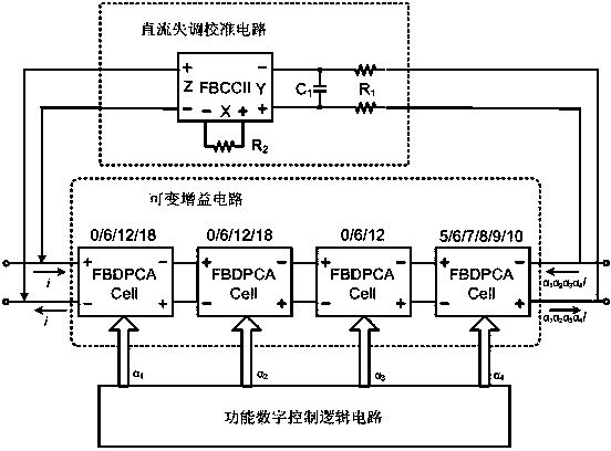
[0020] like figure 1 As shown, a current mode variable gain amplifier includes a variable gain circuit, a functional digital control logic circuit and a DC offset calibration circuit. It is difficult to achieve very high gain for a single-stage current amplifier, and the output linearity will vary with the gain. To achieve high gain with a single-stage amplifier, the stability will inevitably decrease, and the linearity will be limited, so it is necessary to use a multi-stage amplifier cascaded to form. The more stages, the working current of the whole circuit will increase, increasing the power consumption of the circuit. To balance stability, linearity and power consumption, the variable gain circuit is composed of four-stage current fully differential programmable amplifier (FBDPCA, Full Balanced Digital Programmable Current Amplifier); each stage has a gain of A ...


PUM


Abstract

The invention discloses a novel variable gain amplifier circuit in a current mode. The variable gain amplifier circuit comprises a variable gain circuit, a functional digital control logic circuit and a direct current offset calibration circuit, wherein the variable gain circuit comprises four full balanced digital programmable current amplifiers; the functional digital control logic circuit is used for coding a control signal into a binary signal and then controlling gain decibels of the variable gain circuit; and the direct current offset calibration circuit feeds a low-frequency signal output by the variable gain circuit back to an input end of the variable gain circuit to form a negative feedback loop. In the amplifier circuit in the current mode, signal input is low resistance, signal output is high resistance, and a circulating signal is a current signal and is not influenced by the magnitude of voltage. A variable gain amplifier in the current mode is in a Class-AB output structure, so that the power consumption of the circuit is greatly reduced. The current amplifier is free from limitation of a gain bandwidth product, so that the bandwidth is not limited on any gain almost.

Description

technical field [0001] The invention relates to a gain amplifier, in particular to a current mode variable gain amplifier. Background technique [0002] With the improvement of the technology, the withstand voltage of the MOS tube is getting lower and lower, resulting in a reduction of the power supply voltage. For example, the voltage of the popular 40nm low-voltage tube is only about 1.0V, and the turn-on voltage Vt is about 0.4V. In this way, for the amplifier circuit with two layers of tubes, there is only a dynamic range of 0.2V. From the voltage signal point of view, this brings great challenges to the circuit design. [0003] Traditional voltage signal variable gain amplifiers are all realized by op amp feedback. are limited by the gain-bandwidth product of the op amp. When the gain is low, the bandwidth is relatively wide, and when the gain is high, the bandwidth becomes narrow, which is not conducive to the application of broadband applications. Contents of th...

Claims


Application Information

Patent Timeline
Patent Type & Authority Applications(China)
IPC IPC(8): H03F3/45H03F1/26H03F1/34
CPCH03F1/26H03F1/34H03F3/45076H03F3/45479
Inventor 徐建周正吴毅强韩婷婷马力田密王志功陈建平吉荣新
Owner SOUTHEAST UNIV
Why Eureka
Try Eureka