Planar magnetron sputtering target

A magnetron sputtering and planar technology, which is applied in sputtering plating, ion implantation plating, metal material coating technology, etc., can solve the problem of low utilization rate of magnetron sputtering targets, and avoid magnetic short circuit phenomenon , Reasonable layout and stable work

Active Publication Date: 2015-03-11
HOHAI UNIV
View PDF9 Cites 4 Cited by
  • Summary
  • Abstract
  • Description
  • Claims
  • Application Information

AI Technical Summary

Problems solved by technology

[0004] The technical problem to be solved: the present invention aims at the relatively low utilization rate of the magnetron sputtering target, and it is necessary to scientifically and rationally design the magnetron sputtering target in order to effectively increase the target utilization rate

Method used


Image

  • Planar magnetron sputtering target
  • Planar magnetron sputtering target
  • Planar magnetron sputtering target

Examples


Example Embodiment

[0037] Example 1:

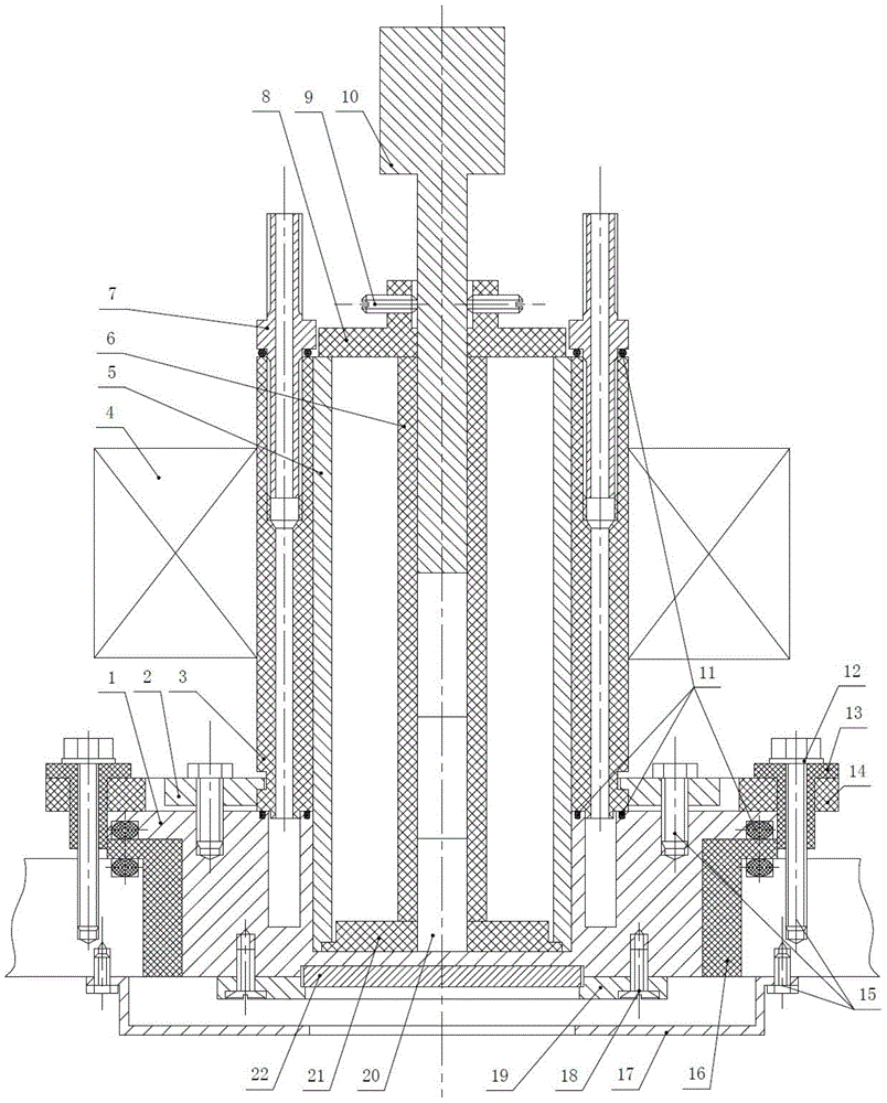
[0038] A planar magnetron sputtering target, which is characterized in that it is composed of a flange 1, a pressure sleeve 2, a water-passing cylinder 3, an excitation coil 4, an electrical pure iron sleeve 5, an insulating sleeve 6, a water nozzle 7, a pressure plate 8, Set screw 9, electrician pure iron pressure rod 10, sealing ring 11, washer 12, insulating sleeve 13, pressure ring 14, bolt 15, insulating spacer 16, shielding cover 17, slotted countersunk screw 18, compression ring 19 , NdFeB permanent magnet column 20 and positioning bracket 21, in which the large end of the positioning bracket 21 is horizontally placed in the circular deep groove in the center of the flange 1; the electrical pure iron sleeve 5 and the positioning bracket 21 are fixed In the circular deep groove in the center of the flange 1; the neodymium iron boron permanent magnet column 20 is stacked in the insulating sleeve 6, one end of the neodymium iron boron permanent magnet colu...

Example Embodiment

[0052] Example 2:

[0053] A plane magnetron sputtering target, the structure is the same as that in Example 1.

[0054] among them:

[0055] ①The insulating sleeve and insulating spacer are processed by polytetrafluoroethylene. Both the insulating sleeve and the insulating spacer are in the shape of a through-bottom, secondary stepped cylindrical cylinder. The total height of the insulating sleeve is 21.5mm, the center hole diameter is Φ6mm, the outer diameter of the small end cylinder is Φ10mm, and the outer diameter and height of the big end cylinder are Φ20mm and 3.5mm respectively. The total height of the insulating spacer is 35mm, the center hole diameter is Φ132mm, the outer diameter of the small end cylinder is Φ150mm, and the outer diameter and height of the big end cylinder are Φ175mm and 5mm respectively.

[0056] ②The pressure ring is processed by phenolic resin, the pressure ring is ring-shaped, its inner diameter and outer diameter are respectively Φ146mm and Φ205mm, th...

Example Embodiment

[0066] Example 3:

[0067] A plane magnetron sputtering target, the structure is the same as that in Example 1.

[0068] among them:

[0069] ①The insulating sleeve and insulating spacer are processed by polytetrafluoroethylene. Both the insulating sleeve and the insulating spacer are in the shape of a through-bottom, secondary stepped cylindrical cylinder. The total height of the insulating sleeve is 21.5mm, the center hole diameter is Φ6mm, the outer diameter of the small end cylinder is Φ10mm, and the outer diameter and height of the big end cylinder are Φ20mm and 3.5mm respectively. The total height of the insulating spacer is 35mm, the center hole diameter is Φ132mm, the outer diameter of the small end cylinder is Φ150mm, and the outer diameter and height of the big end cylinder are Φ175mm and 5mm respectively.

[0070] ②The pressure ring is processed by phenolic resin, the pressure ring is ring-shaped, its inner diameter and outer diameter are respectively Φ146mm and Φ205mm, th...


PUM


Abstract

The invention discloses a planar magnetron sputtering target, which is composed of a flange, a pressing sleeve, a water cylinder, an excitation coil, an electrical pure iron sleeve, an insulating sleeve, a water nozzle, a pressure plate, a set screw, an electrical pure iron pressure rod, a sealing ring, a gasket, an insulating cover, a pressing ring, bolts, an insulating spacer sleeve, a shielding cover, slotted countersunk head screws, a compressing ring, a neodymium iron boron permanent magnet column, and a positioning bracket part. The planar magnetron sputtering target is unique in shielding cover design, structural arrangement of the excitation coil, electrical pure iron sleeve and permanent magnet, magnetic field adjustability of the magnetron sputtering target, cooling structure design and other aspects, solves the common defects of point discharge, low sputtering rate on magnetic materials, complex cooling structure and the like frequently encountered by magnetron sputtering targets, and improves the target material utilization rate. The planar magnetron sputtering target provided by the invention has the characteristics of simple structure, stable and reliable work, large magnetic field adjustable range, high sputtering efficiency, convenient maintenance and low cost, and can be widely applied to vacuum magnetron sputtering coating equipment.

Description

technical field [0001] The invention provides a planar magnetron sputtering target, which belongs to the technical field of vacuum sputtering coating. Background technique [0002] Magnetron sputtering is an important coating technology in the field of vacuum coating. It has the advantages of low temperature, high speed, low energy consumption, wide range of applicable substrates and coating materials, dense film layer, high finish, and good bonding force. Magnetron sputtering coating mainly applies the principle of Penning discharge, by applying a magnetic field in the discharge space, the charged particles (electrons, ions) are bound in the discharge space, and the ionization rate of the charged particles to neutral atoms (molecules) is increased, so that The gas pressure and voltage required for glow discharge are reduced, and the magnetic field on the target surface binds the secondary electrons on the target surface, increasing the bombardment of the secondary electrons...

Claims


Application Information

Patent Timeline
IPC IPC(8): C23C14/35
CPCC23C14/3407C23C14/35
Inventor 王刚江少群王泽华周泽华程江波
Owner HOHAI UNIV
Why Eureka
Try Eureka