Impeller-directly-driven wind-driven generator

A technology for wind turbines and impellers, which is applied to wind turbine components, wind turbines, wind turbine combinations, etc., can solve the problem that the electric power and frequency are difficult to maintain stable, the technical difficulty of large-megawatt converters is difficult, and the wind turbines are restricted. Development and other issues, to achieve the effect of optimizing product function adjustment, light weight and simple structure

Inactive Publication Date: 2015-03-11
DALIAN DESIGN INST CO LTD CHINA FIRST HEAVY IND +1
View PDF6 Cites 12 Cited by
  • Summary
  • Abstract
  • Description
  • Claims
  • Application Information

AI Technical Summary

Problems solved by technology

However, due to the time-varying and seasonal nature of the wind speed, it is difficult to maintain the stability of the power and frequency of the electric energy generated by the wind generator. To connect the wind generator to the grid, converters and transformers are needed to convert the generated electric energy The voltage and frequency required by the power grid, due to the high technical difficulty and high cost of large megawatt converters, and the fact that wind power generation still has no wind during the peak period of social electricity consumption, and relatively strong wind during the low peak period, due to the Storage is very difficult, which seriously restricts the development of wind turbines

Method used


Image

  • Impeller-directly-driven wind-driven generator
  • Impeller-directly-driven wind-driven generator
  • Impeller-directly-driven wind-driven generator

Examples


Embodiment Construction

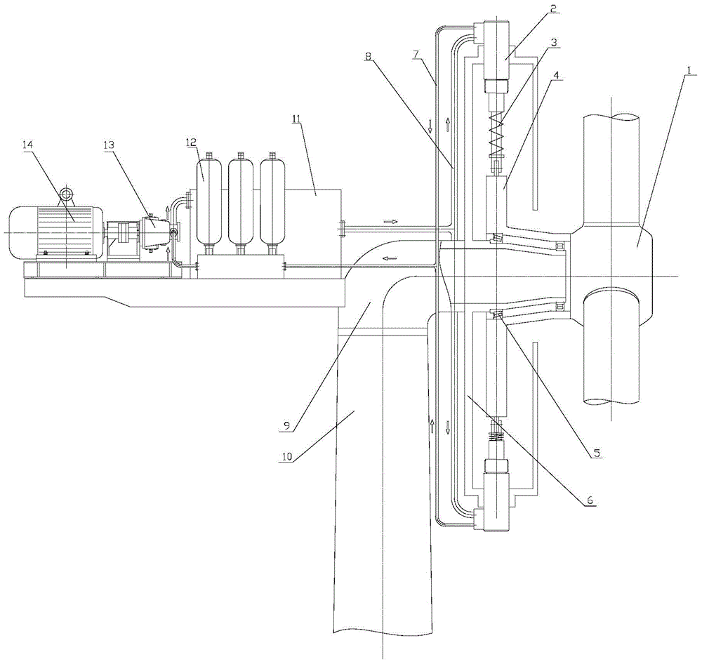
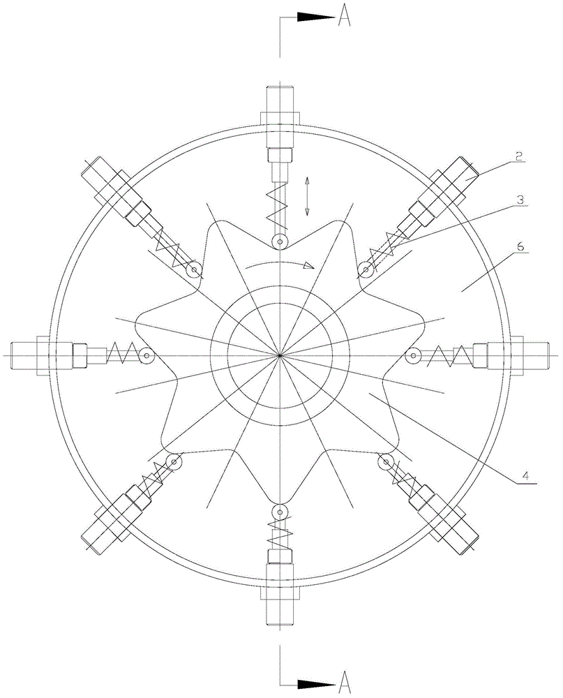
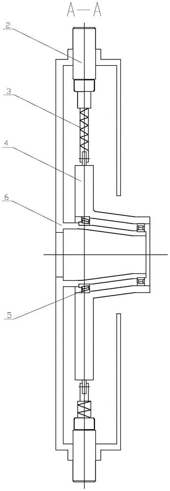
[0018] The present invention will be further described below in conjunction with accompanying drawing. During the work of the present invention, the wind-driven blade drives the impeller 1 to rotate, and the impeller 1 drives the cam turntable 4 to rotate. There are 8 hydraulic cylinders 2 evenly distributed around the cam turntable 4. The cylinder body is installed on the bracket 6, and the bracket 6 is fixed on the main frame 9. The plunger of the hydraulic cylinder 2 is in contact with the cam turntable 4 through the roller installed on the plunger. At the same time, a spring 3 is installed on the plunger to ensure that the roller and the cam turntable 4 are always attached. When the cam turntable 4 rotates, the cam turntable 4 drives the piston of the hydraulic cylinder 2 to reciprocate, thereby realizing the process of converting mechanical energy into hydraulic energy. . The high-pressure oil generated by the hydraulic cylinder 2 is transmitted to the high-speed hydraul...


PUM


Abstract

The invention discloses an impeller-directly-driven wind-driven generator. The wind-driven generator comprises a fan impeller, hydraulic cylinders, a cam turntable, a high-pressure oil circuit, a low-pressure oil circuit, a main frame, a tower tube, an oil tank, energy accumulators, a high-speed hydraulic motor and a generator, wherein pistons of the hydraulic cylinders are in contact with the cam turntable, the high-pressure oil circuit is connected with the hydraulic cylinders and the energy accumulators, the low-pressure oil circuit is connected with the hydraulic cylinders and the oil tank, the energy accumulators are connected with the high-speed hydraulic motor, the oil tank is connected with the high-speed hydraulic motor, and the high-speed hydraulic motor is connected with the generator. The impeller-directly-driven wind-driven generator has the advantages that the difficulties in the prior art are overcome by using a hydraulic transmission technology; firstly, unstable wind energy is converted into a stable revolving speed, which is required by a power-frequency generator, through hydraulic-volume speed regulating, so that constant-frequency control for the generator is effectively realized; secondly, hydraulic transmission is flexible power transmission, thus, a power generation system can be flexible in layout and convenient in mounting, the optimal allocation of resources and the extension of product function adjustment are facilitated, multi-aspect control can be further carried out, and then, stable system pressure and continuous power generation are realized.

Description

technical field [0001] The invention relates to a large megawatt land and sea wind power generation technology, in particular to a wind power generator directly driven by an impeller. Background technique [0002] With the society's attention to environmental issues and energy crisis, wind energy has a high utilization value as a clean energy. In order to improve the generating power and generating efficiency of wind power plants, the single unit power of wind power generators is developing in the direction of high power. Existing wind power generators generally drive the speed increaser by the impeller and then drive the generator, and the impeller directly drives the wind power generator, which is the so-called direct drive fan (the fan without the speed increaser is called a direct drive fan). At present, the power of a single wind turbine has reached several megawatts, and the diameter of the impeller has reached hundreds of meters. However, due to the time-varying and...

Claims


Application Information

Patent Timeline
Patent Type & Authority Applications(China)
IPC IPC(8): F03D9/02F03D11/02
CPCY02E10/72
Inventor 韩长伟高德忠宋清玉
Owner DALIAN DESIGN INST CO LTD CHINA FIRST HEAVY IND
Why Eureka
Try Eureka