
Imaging spectrometer optical splitting system based on single free curved surface

An imaging spectrometer and spectroscopic system technology, applied in spectrometry/spectrophotometry/monochromator, instrument, scientific instrument, etc., can solve the problems of light energy loss, long development cycle, and low system light energy utilization rate , to achieve the effect of excellent performance, smooth channels and mature technology

Active Publication Date: 2015-03-11
SHANGHAI INST OF TECHNICAL PHYSICS - CHINESE ACAD OF SCI
View PDF8 Cites 5 Cited by
  • Summary
  • Abstract
  • Description
  • Claims
  • Application Information

AI Technical Summary

Problems solved by technology

[0005] In addition, other spectrometer splitting systems based on planar gratings generally increase the degree of freedom of the balance system by adding components. The system is relatively complex and requires the introduction of multiple sets of lenses or prisms. The slight inclination and eccentricity of each prism or lens will give The image quality of the system will have a serious impact, which will inevitably lead to difficulties in the installation and testing of the entire system, long development cycle and high development costs.
In addition, the light has to go through multiple refractions and reflections to reach the detector. Each refraction and reflection will bring about the loss of light energy, which will inevitably lead to low utilization of light energy in the system.

Method used


Image

  • Imaging spectrometer optical splitting system based on single free curved surface
  • Imaging spectrometer optical splitting system based on single free curved surface
  • Imaging spectrometer optical splitting system based on single free curved surface

Examples


Embodiment Construction

[0025] Below in conjunction with accompanying drawing and embodiment the present invention is described in further detail:

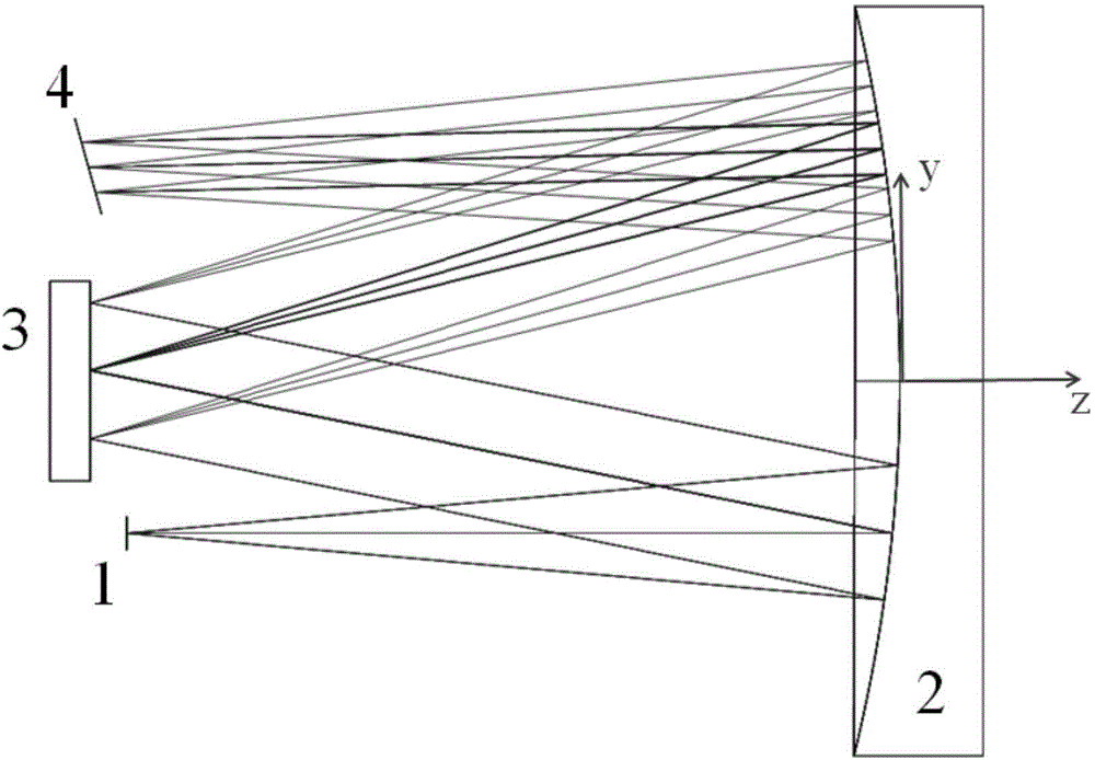
[0026] Such as figure 1 As shown, the spectrometer light-splitting system of the present invention takes the high-performance, simple-structured convex grating Offner structure and the Czerny-Turner structure based on the planar grating as design prototypes, takes the advantages of the two, avoids its shortcomings, and realizes that the number of components is relatively small. High-performance optical splitting under the premise of less and simple system structure. The spectroscopic system includes a slit 1 , a free-form surface mirror 2 , a plane blazed grating 3 and an image surface 4 . The slit 1 is the focal plane of the front telescopic objective lens. The incident light beam from a distant target is imaged on the slit 1 through the telescope as the object plane of the spectroscopic system; the free-form surface mirror 2 is used twice, acting as a...


PUM


Abstract

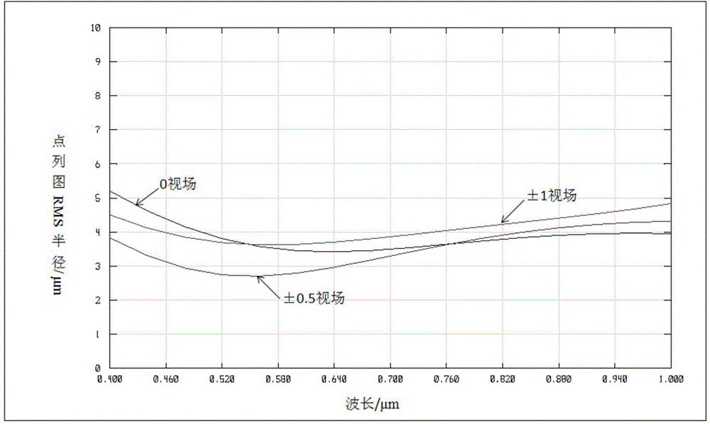
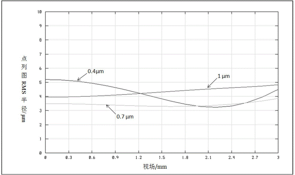
The invention discloses an imaging spectrometer optical splitting system based on a single free curved surface. The system is composed of an entrance slit, a free curved surface reflecting mirror, plane blazed grating and an image surface. The system is characterized in that one non-rotational symmetric free curved surface reflecting mirror is used for two times to act as a collimating mirror and an imaging mirror respectively, and plane blazed grating which is high in performance and mature in processing technology is used cooperatively so that the spectrometer optical splitting system which is simple and compact in structure, small in aberration, low in distortion and high in efficiency is realized. According to the embodiment of the imaging spectrometer optical splitting system based on the single free curved surface, great spectral imaging is realized in 400-1000nm visible near-infrared spectrum so that spherical aberration, coma aberration, astigmatism, spectral distortion and spectral line bending are greatly corrected under the premise that the system is ensued to be simple and compact. The imaging spectrometer optical splitting system based on the single free curved surface can be applied to the field of hyper-spectral imaging of spaceflight and aviation.

Description

technical field [0001] The invention belongs to the field of imaging spectrometer design, and specifically relates to the optical design of a novel imaging spectrometer spectroscopic system based on a single free-form surface and a planar blazed grating. The spectrum of the embodiment of the invention is in the visible and near-infrared, and it is also suitable for short-wave infrared and short-wave infrared. Design of spectroscopic components for spectral imaging systems such as thermal infrared and other spectral bands. Background technique [0002] Imaging spectrometer is an organic combination of imaging technology and spectral technology. It can simultaneously obtain two-dimensional spatial information and one-dimensional spectral information of the target to form a data cube, which is widely used in social production, military activities, space and astronomical exploration, and aerospace. remote sensing and many other fields. Its optical system is generally composed o...

Claims


Application Information

Patent Timeline
Patent Type & Authority Applications(China)
IPC IPC(8): G01J3/02
Inventor 侯佳何志平袁立银况耀武舒嵘张小卫陈爽
Owner SHANGHAI INST OF TECHNICAL PHYSICS - CHINESE ACAD OF SCI
Learn More