
Hydrate formation monitoring method and system based on optics

A hydrate generation and monitoring system technology, applied in the direction of color/spectral characteristic measurement, etc., can solve the problems of high cost, large drift, low sensitivity, etc., to improve the measurement accuracy, reduce the volume of the gas chamber, and increase the absorption optical path Effect

Active Publication Date: 2015-03-11
SOUTH CHINA UNIV OF TECH
View PDF3 Cites 2 Cited by
  • Summary
  • Abstract
  • Description
  • Claims
  • Application Information

AI Technical Summary

Problems solved by technology

The main advantage of the electrochemical sensor is the high sensitivity and good selectivity of the gas. The disadvantage is that the higher the sensitivity, the larger the drift and the faster the attenuation.
However, the designed gas absorption path is often too small and the sensitivity is very low. Even if the absorption path is increased, the detection equipment will be too large and the cost will be high.

Method used


Image

  • Hydrate formation monitoring method and system based on optics
  • Hydrate formation monitoring method and system based on optics
  • Hydrate formation monitoring method and system based on optics

Examples


Embodiment 1

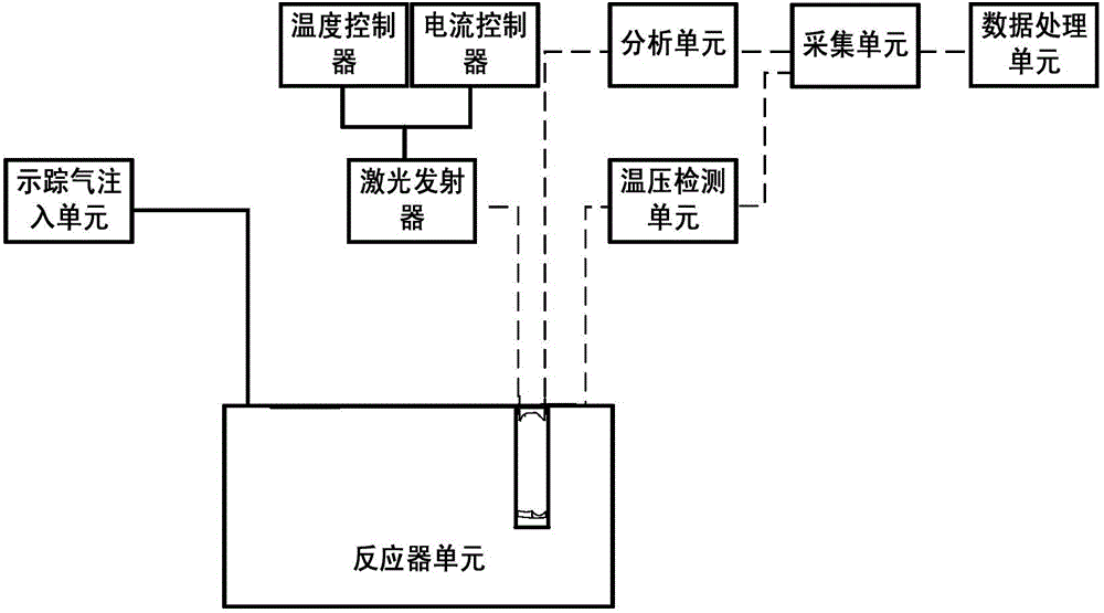
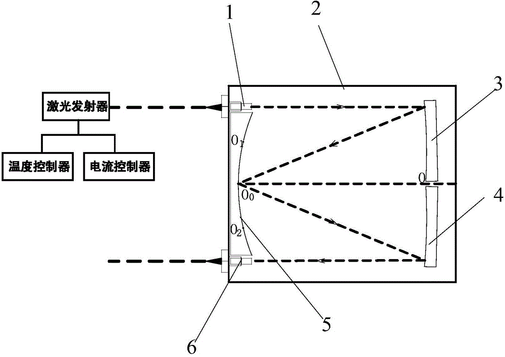
[0038] Such as figure 1 and figure 2As shown, an optical-based hydrate formation monitoring system includes a tracer gas injection unit that injects tracer gas into the reactor unit, and is used to input and output laser light into the reactor unit to track the tracer gas in the reactor unit. Hydrate formation monitoring unit for gas concentration changes, analysis unit for detecting the intensity of laser light emitted by the hydrate formation monitoring unit, temperature and pressure detection unit for detecting temperature and pressure in the reactor unit, temperature and pressure detection unit for collecting and analyzing unit data collection unit, and a data processing unit for processing the data collected by the collection unit so as to judge whether there is hydrate formation therein, the hydrate formation monitoring unit includes a laser emitter, a gas permeable gas set in the reactor unit Chamber 2, the gas chamber 2 includes a White cell for the gas to absorb las...

Embodiment 2

[0046] A method for monitoring hydrate formation based on the system, comprising the steps of:

[0047] Inject tracer gas into the reactor unit through the tracer gas injection unit;

[0048] The laser emitter emits a laser with a certain frequency and enters the air chamber 2 through the incident optical fiber and the first self-focusing lens 1, and is reflected by each concave lens in the air chamber 2. After being coupled by the second self-focusing lens 6, it is emitted through the outgoing optical fiber;


PUM

PropertyMeasurementUnit
Wavelengthaaaaaaaaaa

Abstract

The invention discloses a hydrate formation monitoring system based on optics. The system comprises a tracer gas introduction unit, a hydrate formation monitoring unit, an analytic unit, a temperature and pressure detection unit, an acquisition unit and a data processing unit, wherein the hydrate formation monitoring unit comprises a laser emitter and a breathable gas chamber formed in a reactor unit; a white cell used for absorbing laser by gas, a first self-focusing lens used for collimating and coupling laser emitted into the gas chamber, and a second self-focusing lens used for collimating and coupling laser reflected in the white cell and emitting the laser from the gas chamber are arranged in the gas chamber. The invention further provides a hydrate formation monitoring method based on optics. According to the hydrate formation monitoring method and system, by introducing a certain amount of the tracer gas which easily forms hydrate into the reactor unit, detecting the concentration change of the tracer gas before and after reaction in the reactor unit and combining the temperature and pressure change, whether the hydrate is formed in the reactor unit or not is judged, so that a monitoring result is relatively reliable and the precision is relatively high.

Description

technical field [0001] The invention relates to a method and system for monitoring hydrate formation using tracer gas, in particular to an optical-based hydrate formation monitoring method and system. Background technique [0002] In the oil and gas industry, the research on gas hydrate has practical significance. After the natural gas produced from the gas well passes through the throttling valve to reduce the pressure and temperature, in the long-distance gas transmission pipeline and oil field gas gathering pipeline network, gases such as carbon dioxide, hydrogen sulfide and low molecular weight hydrocarbons can be released under certain temperature and pressure conditions. Hydrates will be formed, thereby blocking equipment and gas pipelines, which will not only affect the smooth progress of production, but also cause safety accidents. Therefore, in order to prevent the economic losses caused by the blockage of natural gas pipelines due to the formation of hydrates, it ...

Claims


Application Information

Patent Timeline
IPC IPC(8): G01N21/31
Inventor 樊栓狮陈乐求郎雪梅王燕鸿
Owner SOUTH CHINA UNIV OF TECH
Learn More