
Detection Method of Salient Pole Characteristics of Permanent Magnet Synchronous Motor Using Pulse High Frequency Voltage Injection

A technology of permanent magnet synchronous motor and salient pole characteristics, applied in the field of detection, can solve the problems of deviation of actual characteristics, time-consuming simulation calculation, complicated design, etc., and achieve the effect of improving operation accuracy, optimizing operation range and short detection period.

Active Publication Date: 2017-08-01
SHANGHAI HUACHENG ELEVATOR TECH CO LTD
View PDF5 Cites 0 Cited by
  • Summary
  • Abstract
  • Description
  • Claims
  • Application Information

AI Technical Summary

Problems solved by technology

Generally, the required inductance value is obtained by finite element analysis (FEA) or detection method before analysis, but the former requires a lot of time for simulation calculation, and there may still be considerable deviations from the actual characteristics, while the latter requires cumbersome design and research

Method used


Image

  • Detection Method of Salient Pole Characteristics of Permanent Magnet Synchronous Motor Using Pulse High Frequency Voltage Injection
  • Detection Method of Salient Pole Characteristics of Permanent Magnet Synchronous Motor Using Pulse High Frequency Voltage Injection
  • Detection Method of Salient Pole Characteristics of Permanent Magnet Synchronous Motor Using Pulse High Frequency Voltage Injection

Examples


Embodiment Construction

[0032] The present invention will be described in detail below in conjunction with specific embodiments. The following examples will help those skilled in the art to further understand the present invention, but do not limit the present invention in any form. It should be noted that those skilled in the art can make several modifications and improvements without departing from the concept of the present invention. These all belong to the protection scope of the present invention.

[0033] The embodiments of the present invention are further described below in conjunction with the accompanying drawings: this embodiment is implemented on the premise of the technical solution of the present invention, and detailed implementation methods and specific operating procedures are provided, but the protection scope of the present invention is not limited to the following the embodiment.

[0034] In this embodiment, the method for detecting salient pole characteristics of a permanent mag...


PUM


Abstract

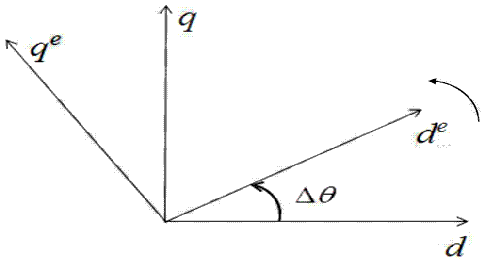
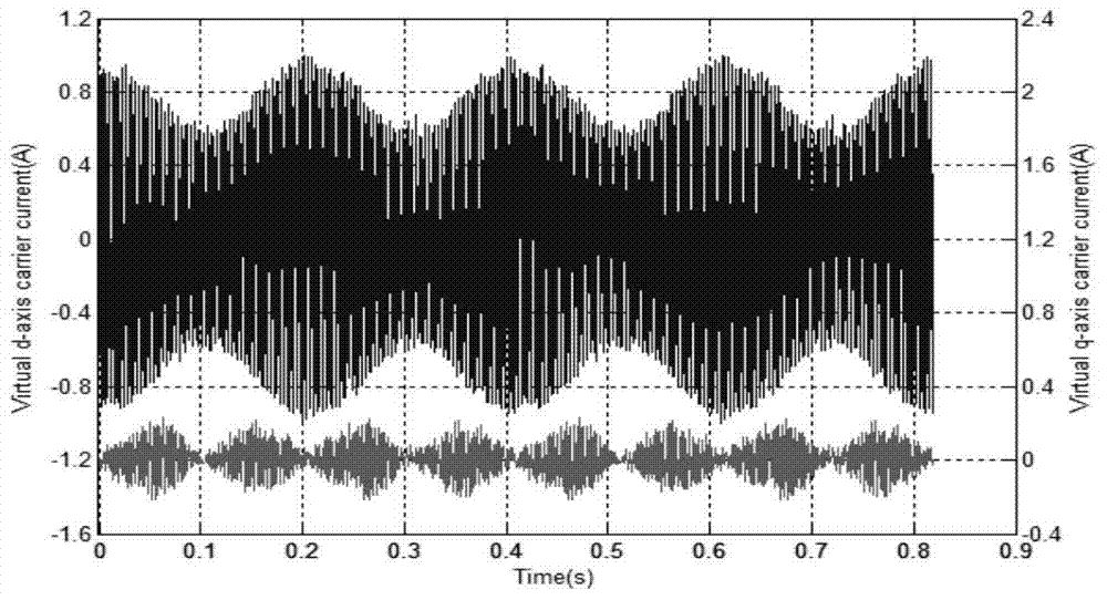
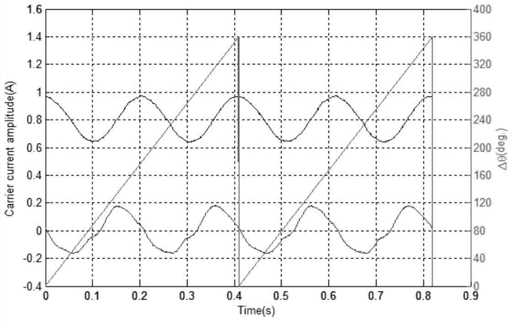
The invention provides a permanent magnet synchronous motor salient pole property detection method based on pulsating high frequency voltage injection. The permanent magnet synchronous motor salient pole property detection method based on the pulsating high frequency voltage injection includes following steps: fixing the position of a rotor of a permanent magnet synchronous motor to be detected, and preventing the position of the rotor from changing when the rotor is under external force; respectively forming a d axis current id and a q axis current iq under corresponding work points on the d axis and the q axis of the permanent magnet synchronous motor to be detected by using current closed loop control after the permanent magnet synchronous motor and a drive device are powered on; building an estimated de-qe axis coordinate system, anticlockwise and periodically rotating the de-qe axis coordinate system at low frequency relatively to a d-q axis coordinate system of the permanent magnet synchronous motor, representing an intersection angle between the de-qe axis coordinate system and the d-q axis coordinate system as delta theta, and increasing the intersection angle delta theta from 0 to 2pi by rotating the de-qe axis coordinate system by one revolution around the d-q axis coordinate system; applying high frequency voltage signals and the like on the de axis in the de-qe axis coordinate system which keeps rotation anticlockwise through space vector pulse width modulation. The permanent magnet synchronous motor salient pole property detection method based on the pulsating high frequency voltage injection not only simplifies and conveniently detects salient pole properties of the permanent magnet synchronous motor under different work points, but also can detect influences of cross saturation effects on salient pole shifting of the permanent magnet synchronous motor under the different work points.

Description

technical field [0001] The invention relates to a detection method, in particular to a detection method for salient pole characteristics of a permanent magnet synchronous motor using pulse vibration high-frequency voltage injection. Background technique [0002] Existing position sensorless control methods for permanent magnet synchronous motors (Permanent Magnet Synchronous Motor, PMSM) based on motor back EMF, such as back EMF method, model reference adaptive method, flux observer method, etc., when the motor is running at low speed or zero When the speed is high, these control methods fail because the back electromotive force of the motor is small or zero. The position sensorless control method based on high-frequency signal injection relies on the salient pole characteristics of the motor, does not depend on motor parameters and back EMF, and realizes high-precision control at low and zero speeds through position estimation, so it has broad application prospects. [000...

Claims


Application Information

Patent Timeline
Patent Type & Authority Patents(China)
IPC IPC(8): H02P21/14G01R31/34
Inventor 林环城王志新
Owner SHANGHAI HUACHENG ELEVATOR TECH CO LTD
Learn More