
Driving system of high-voltage permanent magnet synchronous motor

A permanent magnet synchronous motor and drive system technology, applied in the direction of single motor speed/torque control, emergency protection circuit device for limiting overcurrent/overvoltage, electrical components, etc.

Active Publication Date: 2015-03-11
UNITED AUTOMOTIVE ELECTRONICS SYST
View PDF3 Cites 22 Cited by
  • Summary
  • Abstract
  • Description
  • Claims
  • Application Information

AI Technical Summary

Problems solved by technology

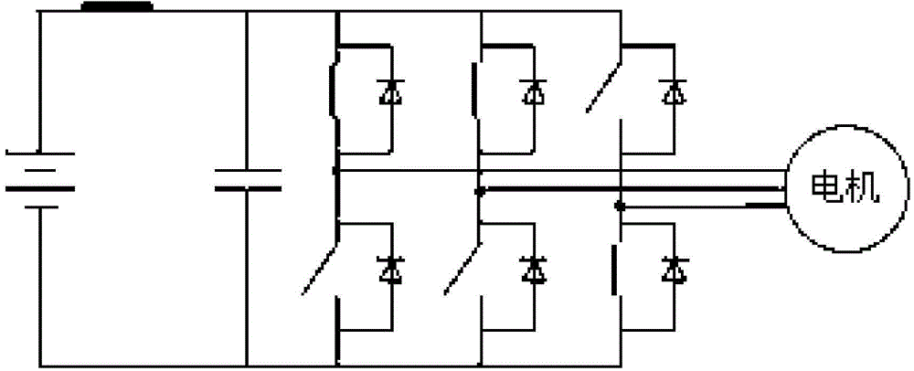
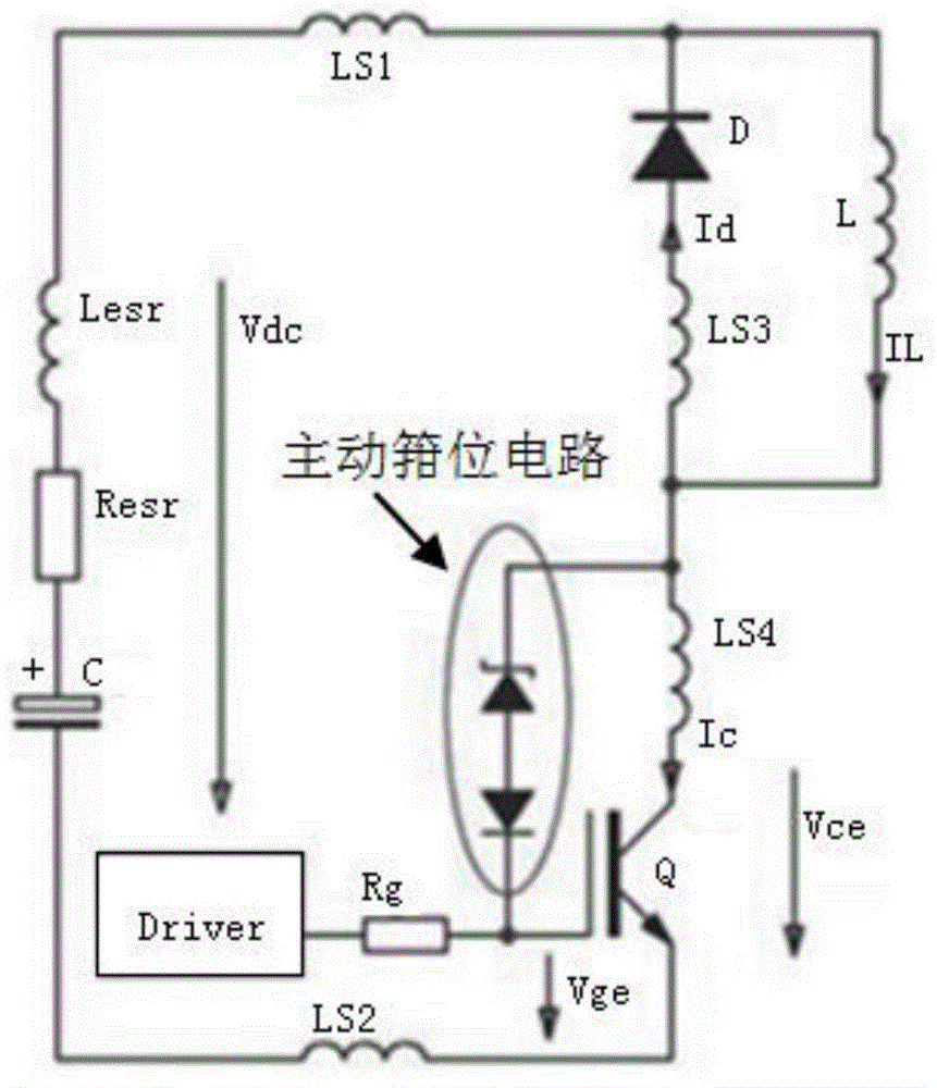
The lower three-tube short-circuit (ASC, Active short circuit) mode and the upper three-tube IGBT active clamping circuit (Active Clamping) circuit take effect at the same time, resulting in a straight-through of the upper and lower bridge arms, and the transient current may exceed 2000A, such as Image 6 As shown, the switching tube (IGBT) will be broken down within a few microseconds

Method used


Image

  • Driving system of high-voltage permanent magnet synchronous motor
  • Driving system of high-voltage permanent magnet synchronous motor
  • Driving system of high-voltage permanent magnet synchronous motor

Examples


Embodiment 1

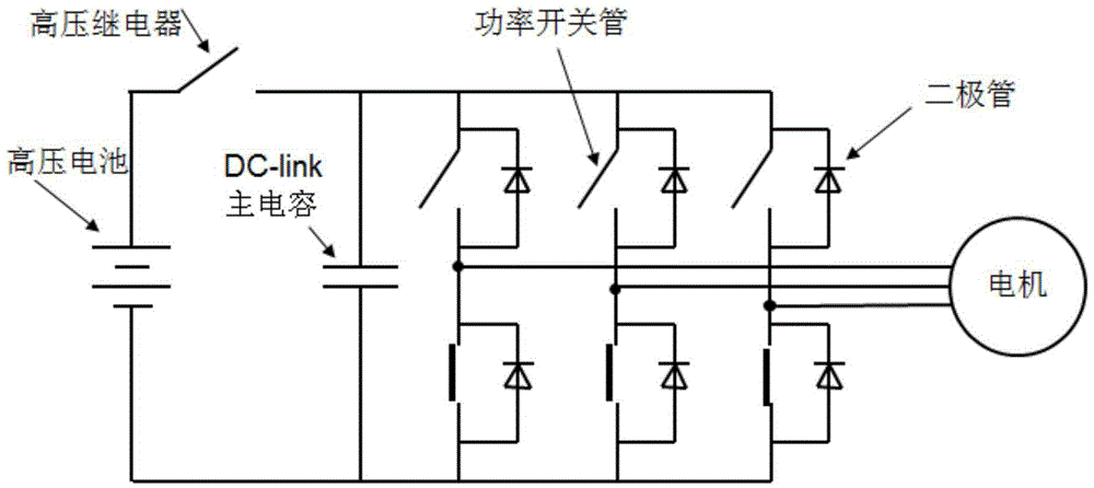
[0038] High-voltage permanent magnet synchronous motor drive system, including high-voltage relay (Main Relay), main capacitor, three-phase bridge AC inverter circuit, motor controller, active clamp circuit;

[0039] The main capacitor is connected in parallel with the three bridge arms of the three-phase bridge AC inverter circuit and is connected in series with the high-voltage relay at both ends of the high-voltage battery;

[0040] The power tube of the three-phase bridge AC inverter circuit adopts IGBT (insulated gate bipolar transistor), the gate (G pole) and the collector (C pole) of the three IGBTs of the upper bridge arm of the three bridge arms An active clamp circuit is set between;

[0041] The motor controller, when the high-voltage relay (Main Relay) is cut off, enters the fast active discharge mode;

[0042]The motor controller, in the fast active discharge mode, if the voltage at both ends of the main capacitor exceeds the clamping threshold, it immediately co...

Embodiment 2

[0049] Based on the high-voltage permanent magnet synchronous motor drive system of the first embodiment, when the drive system fails (for example, the permanent magnet synchronous motor drive system has an overvoltage fault, an overtemperature fault, a sensor signal loss fault, etc.), the motor controller immediately controls the The three IGBTs of the lower bridge arm of the three bridge arms of the three-phase bridge AC inverter circuit are all turned on, the three IGBTs of the upper bridge arm are all turned off, and the three-tube short circuit (ASC, Active short circuit) mode is entered, and at the same time Send a request to cut off the high voltage relay (Main relay) to the vehicle controller (VCU);

[0050] The vehicle controller (VCU), after receiving the request to cut off the high-voltage relay (Main relay), controls the high-voltage relay to cut off, and outputs a high-voltage relay cut-off signal to the motor controller;

[0051] The motor controller enters the f...

Embodiment 3

[0055] Based on the high-voltage permanent magnet synchronous motor drive system of the first embodiment, the motor controller includes a microcontroller and a complex programmable logic device (CPLD);

[0056] After the motor controller enters the fast active discharge mode, the working process is as follows:

[0057] (1) The complex programmable logic device logic triggers fault interrupt;

[0058] (2) The microcontroller identifies the fault interruption, and sends a six-tube freewheeling command to control all six IGBTs of the three bridge arms of the three-phase bridge AC inverter circuit to be disconnected, and counts in n milliseconds After that, send the command to release the six-tube full break (Freewheeling) to exit this state;

[0059] (3) The complex programmable logic device (CPLD) recognizes the release six-tube freewheeling command, and controls all the three IGBTs of the lower bridge arm of the three bridge arms of the three-phase bridge AC inverter circuit ...


PUM


Abstract

The invention discloses a driving system of a high-voltage permanent magnet synchronous motor. A main capacitor and a high-voltage relay are connected in series at two ends of a high-voltage battery after the main capacitor is in parallel connection with three bridge arms of a three-phase bridge-type alternating-current inverter circuit; an active clamping circuit is arranged between gate poles and collectors of three IGBTs (insulated gate bipolar transistors) of upper bridge arms of the bridge arms of the three-phase bridge-type alternating-current inverter circuit; a motor controller enters a rapid active discharging mode after the high-voltage relay is switched off; if the voltage at two ends of the main capacitor exceeds a clamping threshold, all the six IGBTs of the bridge arms of the three-phase bridge-type alternating-current inverter circuit are immediately controlled to be switched off, and after n milliseconds, all the three IGBTs of the lower bridge arms are controlled to be switched on and all the three IGBTs of the upper bridge arms are controlled to be switched off. The driving system of the high-voltage permanent magnet synchronous motor protects power devices from being broken down by transient-state high voltages when the high-voltage relay is switched off and protects the power devices from being broken down by transient-state high-voltage surges when the high-voltage relay is switched on unexpectedly.

Description

technical field [0001] The invention relates to new energy vehicle technology, in particular to a high-voltage permanent magnet synchronous motor drive system. Background technique [0002] Most of the new energy vehicles use a high-voltage permanent magnet synchronous motor drive system exceeding 200VDC. High voltage permanent magnet synchronous motor drive system such as figure 1 As shown in the figure, it includes a high-voltage relay (Main Relay), a main capacitor (DC-link), and a three-phase bridge AC inverter circuit; after the main capacitor is connected in parallel with the three bridge arms of the three-phase bridge AC inverter circuit It is connected in series with the high-voltage relay (Main Relay) at both ends of the high-voltage battery. When an overvoltage failure occurs on the main capacitor (such as more than 450V), the high-voltage relay (Main Relay) is turned on, and the high-voltage permanent magnet synchronous motor drive system will switch from the no...

Claims


Application Information

Patent Timeline
Patent Type & Authority Applications(China)
IPC IPC(8): H02P6/08H02H7/08
CPCH02H7/08H02H9/04
Inventor 何海王萑徐玮刘志明
Owner UNITED AUTOMOTIVE ELECTRONICS SYST
Learn More