Reciprocating grate-fired furnace

A technology of reciprocating grate and layer burning furnace, which is applied in the direction of combustion chamber, combustion method, combustion equipment, etc., to achieve the effect of easy maintenance, reduction of heating area, and reduction of production cost

Inactive Publication Date: 2015-03-18
丹东玉龙镁业有限公司
View PDF8 Cites 2 Cited by
  • Summary
  • Abstract
  • Description
  • Claims
  • Application Information

AI Technical Summary

Problems solved by technology

But at present, anthracite can only be used in fluidized combustion boilers. If it can be used as a fuel for bed-burning furnaces, it will not only reduce the cost, greatly improve the utilization rate of energy, but also have a positive effect on improving economic benefits and market competitiveness.

Method used


Image

  • Reciprocating grate-fired furnace

Examples


Embodiment Construction

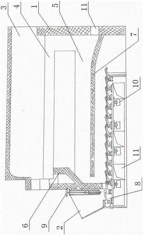
[0017] The present invention will be described in further detail below in conjunction with the accompanying drawings.

[0018] Such as figure 1 As shown, the present invention includes a body of furnace 1, a coal hopper 2, a front arch 6, a rear arch 7, a fire grate 8 and a gate 9, wherein the top of the body of furnace 1 is a boiler 3, and the bottom is a combustion chamber 5. A flue 4 is formed between the 3 and the combustion chamber 5; An opening is provided on the inner wall of the furnace body 1 on one side of the combustion chamber 5, and the coal hopper 2 is arranged outside the opening. The front arch 6, the rear supply 7 and the fire grate 8 are arranged in the combustion chamber 5, wherein the front arch 6 is located Above the opening, one end of the rear arch 7 is affixed to the inner wall of the other side of the body of heater 1, and the other end is a free end, located between the opening and the front arch 6, and the free end is connected to the side of the bo...


PUM


Abstract

The invention belongs to the technical field of combustion furnaces, and particularly relates to a reciprocating grate-fired furnace. The reciprocating grate-fired furnace comprises a furnace body, a coal hopper, a front arch, a rear arch and a grate, wherein a boiler barrel is arranged on the upper portion of the interior of the furnace body, a combustion chamber is arranged on the lower portion of the interior of the furnace body, and a flue is formed between the boiler barrel and the combustion chamber; an opening is formed in the inner wall of the side, with the combustion chamber, of the furnace body, and the coal hopper is arranged outside the opening; the front arch, the rear arch and the grate are arranged in the combustion chamber, the front arch is arranged above the opening, one end of the rear arch is installed on the inner wall of the other side of the furnace body, the other end of the rear arch is a free end and is arranged between the opening and the front arch, and a gap is reserved between the free end and the inner wall on one side of the furnace body; the grate is installed at the bottom of the furnace body, and the coal inlet end of the grate penetrates out of the opening and is arranged below the coal hopper. According to the reciprocating grate-fired furnace, anthracite serves as fuel of the reciprocating grate-fired furnace instead of secondary soft coal, the purposes of energy saving, emission reduction and consumption reduction are achieved, and the production cost can be reduced to a large extent.

Description

technical field [0001] The invention belongs to the field of combustion furnaces, in particular to a reciprocating grate layer combustion furnace. Background technique [0002] At present, most of the boilers commonly used in domestic industrial production are reciprocating grate layer-fired furnaces. The characteristic of this furnace is that it can only use second-class bituminous coal with a calorific value above 5000Kcal / kg. Reaching about 3.33 million yuan, and the coal cannot be completely burned, the production cost is too high. Most of the real estate anthracite is 1800~3600kcal / kg low-quality anthracite, the price is low, the transportation distance is short, and the resources are abundant. However, at present, anthracite can only be used in fluidized combustion boilers. If it can be used as a fuel for bed-fired furnaces, it will not only reduce the cost, greatly improve the utilization rate of energy, but also have a positive effect on improving economic benefits ...

Claims


Application Information

Patent Timeline
Patent Type & Authority Applications(China)
IPC IPC(8): F23B30/10F23M7/00F23M5/06
Inventor 张鸿鑫田玉海田利王冲
Owner 丹东玉龙镁业有限公司
Why Eureka
Try Eureka