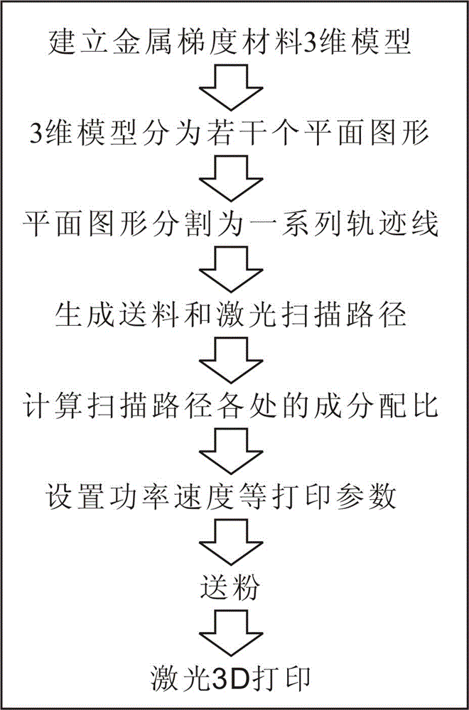
Laser 3D printing manufacturing method of metal gradient material
A gradient material and 3D printing technology, applied in the direction of improving process efficiency and energy efficiency, can solve problems such as preparation difficulties, achieve the effects of avoiding waste, saving raw materials, and improving work efficiency
- Summary
- Abstract
- Description
- Claims
- Application Information
AI Technical Summary
Problems solved by technology
Method used
Image
Examples
Embodiment 1
[0041] The steps of the present invention are:
[0042] 1) modeling
[0043] Establish a computer three-dimensional model diagram of the metal gradient material; slice the model diagram into a series of plane graphics with a thickness of 10 μm according to the actual design requirements; divide the plane graphics into a series of 30 μm trajectory lines; generate laser and feeding materials according to the trajectory lines The scan path of the device;
[0044] 2) Calculate the ratio
[0045] According to the composition design requirements of the gradient material, calculate the component distribution ratio of different positions of the functionally graded structure, and input it into the computer as a variable to control the powder feeding ratio of different positions during printing;
[0046] 3) Set print parameters
[0047] Set the laser power to 200W, the printing speed to 0.2m / s, and the powder feeding volume to 0.06mm 3 / s;
[0048] 4) Powder delivery
[0049] Put ...
Embodiment 2
[0054] The steps of the present invention are:
[0055] 1) modeling
[0056] Establish a computer three-dimensional model diagram of the metal gradient material; slice the model diagram into a series of planar figures with a thickness of 40 μm according to the actual design requirements; divide the planar figures into a series of trajectory lines of 100 μm; generate laser and feeding materials according to the trajectory lines The scan path of the device;
[0057] 2) Calculate the ratio
[0058] According to the composition design requirements of the gradient material, calculate the component distribution ratio of different positions of the functionally graded structure, and input it into the computer as a variable to control the powder feeding ratio of different positions during printing;
[0059] 3) Set print parameters
[0060] Set the laser power to 200W, the printing speed to 0.1m / s, and the powder feeding volume to 0.4mm 3 / s;
[0061] 4) Powder delivery
[0062] Put...
Embodiment 3
[0067] The steps of the present invention are:
[0068] 1) modeling
[0069] Establish a computer three-dimensional model diagram of the metal gradient material; slice the model diagram into a series of plane graphics with a thickness of 80 μm according to the actual design requirements; divide the plane graphics into a series of 200 μm trajectory lines; generate laser and feeding materials according to the trajectory lines The scan path of the device;
[0070] 2) Calculate the ratio
[0071] According to the composition design requirements of the gradient material, calculate the component distribution ratio of different positions of the functionally graded structure, and input it into the computer as a variable to control the powder feeding ratio of different positions during printing;
[0072] 3) Set print parameters
[0073] Set the laser power to 400W, the printing speed to 0.01m / s, and the powder feeding volume to 0.16mm 3 / s;
[0074] 4) Powder delivery
[0075] Pu...
PUM
| Property | Measurement | Unit |
|---|---|---|
| Particle size | aaaaa | aaaaa |
Abstract
Description
Claims
Application Information
 - R&D
- Intellectual Property
- Life Sciences
- Materials
- Tech Scout
- Unparalleled Data Quality
- Higher Quality Content
- 60% Fewer Hallucinations
Browse by: Latest US Patents, China's latest patents, Technical Efficacy Thesaurus, Application Domain, Technology Topic, Popular Technical Reports.
© 2025 PatSnap. All rights reserved.Legal|Privacy policy|Modern Slavery Act Transparency Statement|Sitemap|About US| Contact US: help@patsnap.com

