A catalytic filter element and its preparation method and device and application of the device

A filter element and nano-catalyst technology, which is applied in the field of low temperature flue gas purification, can solve the problems of great influence on the activity and service life of the catalytic filter element, uneven coating of the catalyst, large energy consumption of the catalyst, etc. Improve the effect of implantation

Active Publication Date: 2020-12-01
NANJING WEIHENG EXPERIMENTAL EQUIP CO LTD
View PDF3 Cites 0 Cited by
  • Summary
  • Abstract
  • Description
  • Claims
  • Application Information

AI Technical Summary

Problems solved by technology

It uses paraffin to pretreat the surface of the filter, which can effectively reduce the blockage of the catalyst to the catalytic filter membrane during the impregnation process, but paraffin is a consumable, which increases the cost, and the method of vacuuming the catalyst after impregnation consumes a lot of energy
Both methods are prone to the shortcomings of uneven catalyst coating and uneven heating during drying and calcination, which have a great impact on the activity and service life of the catalytic filter element

Method used


Image

  • A catalytic filter element and its preparation method and device and application of the device
  • A catalytic filter element and its preparation method and device and application of the device
  • A catalytic filter element and its preparation method and device and application of the device

Examples


Embodiment 1

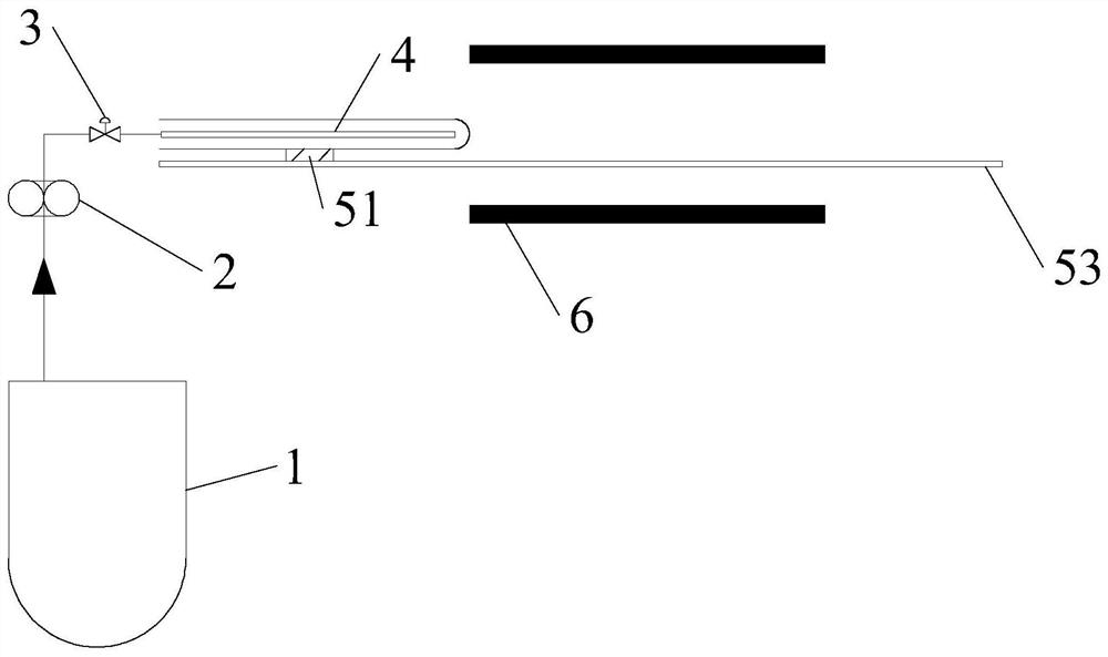
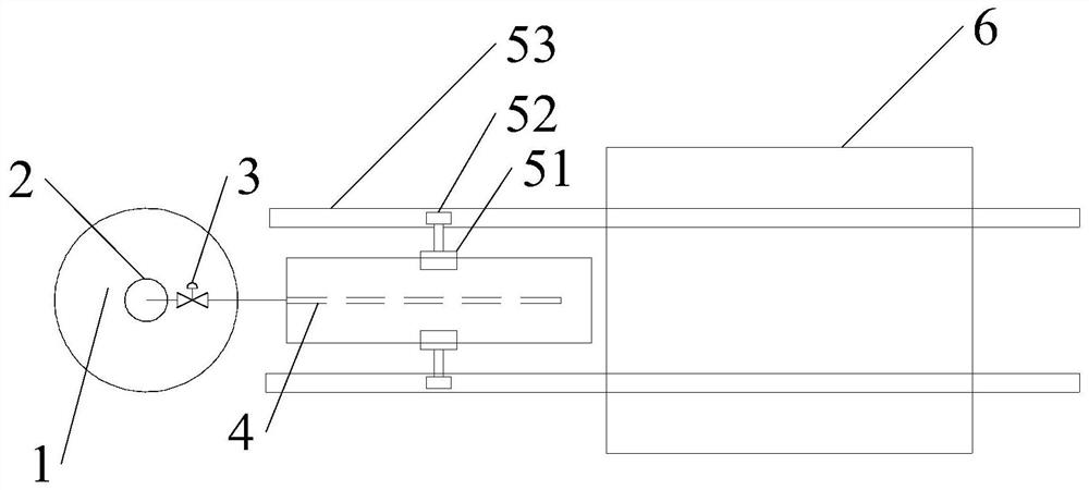
[0055] This embodiment provides a device for preparing a catalytic filter element, the structural schematic diagram of the device is as follows figure 1 and figure 2 As shown, the device includes: a slurry storage unit, a slurry injection unit, a filter element fixing unit and a heating unit.

[0056] An advection pump 2 is arranged between the slurry storage unit and the slurry injection unit, the slurry storage unit is a stirring slurry tank 1, and the slurry injection unit includes a porous slurry injection pipe 4 and an electric valve 3, The inlet of the horizontal flow pump 2 is connected with the outlet of the stirring slurry tank 1 , and the outlet of the horizontal flow pump 2 is connected with the porous slurry injection pipe 4 through the electric valve 3 .

[0057] The filter core fixing unit includes a top-down round roller 51, a moving pulley 52 and a support bracket 53. There are two round rollers 51, one of which is connected with a motor, and the other round ...

Embodiment 2

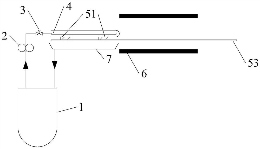
[0060] This embodiment provides a device for preparing a catalytic filter element, the structural schematic diagram of the device is as follows image 3 and Figure 4 As shown, the device includes: a slurry storage unit, a slurry injection unit, a filter element fixing unit and a heating unit.

[0061] An advection pump 2 is arranged between the slurry storage unit and the slurry injection unit, the slurry storage unit is a stirring slurry tank 1, and the slurry injection unit includes a porous slurry injection pipe 4 and an electric valve 3, The inlet of the horizontal flow pump 2 is connected with the outlet of the stirring slurry tank 1 , and the outlet of the horizontal flow pump 2 is connected with the porous slurry injection pipe 4 through the electric valve 3 .

[0062] The filter element fixing unit includes a top-down round roller 51, a moving pulley 52 and a support bracket 53, the number of round rollers 51 is four, one of which is connected with a motor, and the o...


PUM

PropertyMeasurementUnit
pore sizeaaaaaaaaaa
thicknessaaaaaaaaaa
particle sizeaaaaaaaaaa

Abstract

The invention relates to a catalytic filter element, a preparation method and a device thereof and application of the device. The preparation method comprises the following steps that nanometer catalyst slurry is inserted in the inner part of a blank ceramic fiber filter element through an ejecting method, and the catalytic filter element is obtained through heating curing; the device comprises aslurry storage unit, a slurry ejecting unit, a filter element fixing unit and a heating unit, the slurry storage unit is connected with the slurry ejecting unit, a slurry transporting unit is arrangedbetween the slurry storage unit and the slurry ejecting unit, the filter element fixing unit comprises a round roller, a moving sliding wheel and a support bracket which are arranged from top to bottom, and the heating unit is a baking tunnel. According to the catalytic filter element, under the filtering wind speed of 1 m / min, the pressure drop is below 600 Pa, the dust load of filtered gas is below 1 mg / m<3>, and denitration activity can reach above 98% at 250-400 DEG C.

Description

technical field [0001] The invention belongs to the field of low-temperature flue gas purification, and relates to a ceramic fiber filter element, in particular to a catalytic filter element, a preparation method, a device and an application of the device. Background technique [0002] The catalytic filter element has the functions of dust removal and catalysis at the same time. The basic principle is: the dust in the flue gas is filtered and separated by the outer surface of the catalytic filter element, and the dust-free flue gas then undergoes a catalytic reaction with the catalyst loaded inside the filter element to remove pollutants. the goal of. The catalytic filter element can synergistically treat a variety of pollutants, reducing investment, operating costs and floor space, and has become a research hotspot in the purification of flue gas at the tail of small and medium-sized combustion equipment. [0003] The implantation method of the catalytic filter element tha...

Claims


Application Information

Patent Timeline
Patent Type & Authority Patents(China)
IPC IPC(8): B01D39/20B01D46/00B01D53/86B01D53/56B01J23/30
CPCB01D39/2082B01D46/00B01D53/8628B01D2239/0407B01J23/30
Inventor 余剑皇甫林刘周恩李长明高士秋
Owner NANJING WEIHENG EXPERIMENTAL EQUIP CO LTD
Why Eureka
Try Eureka