Internal combustion engine water mist flow control mechanism, water combustion-supporting system and control method of water combustion-supporting system

A water mist flow and control mechanism technology, applied in engine control, internal combustion piston engine, combustion engine, etc., can solve problems such as hindering the normal operation of the engine, increasing fuel consumption, and reducing the combustion-supporting effect of water

Active Publication Date: 2015-03-25
陶华
View PDF5 Cites 3 Cited by
  • Summary
  • Abstract
  • Description
  • Claims
  • Application Information

AI Technical Summary

Problems solved by technology

However, the effect of this method is not stable in actual use. Sometimes it is good and sometimes it is not good. The overall effect is not obvious, and even the fuel consumption increases. Therefore, no related products have entered the market at present
After testing, for a conventional engine that is only connected to a water mist generator, the engine can reduce fuel consumption and carbon dioxide emissions by about 12% under stable conditions; Reduce fuel consumption and carbon dioxide emissions to about 5%
That is to say, in the case of acceleration, the effect of water combustion is greatly reduced
The main reason for the above situation is that drivers (especially large and heavy vehicles) often have to step on the accelerator to the bottom in the actual driving process, which increases the power of the engine air duct to draw air, and also sucks in the excessive air. There are too many water molecules, which affects the combustion-supporting effect of the engine, and even hinders the normal operation of the engine

Method used


Image

  • Internal combustion engine water mist flow control mechanism, water combustion-supporting system and control method of water combustion-supporting system
  • Internal combustion engine water mist flow control mechanism, water combustion-supporting system and control method of water combustion-supporting system
  • Internal combustion engine water mist flow control mechanism, water combustion-supporting system and control method of water combustion-supporting system

Examples


Embodiment Construction

[0043] The present invention will be further described below in conjunction with specific embodiments.

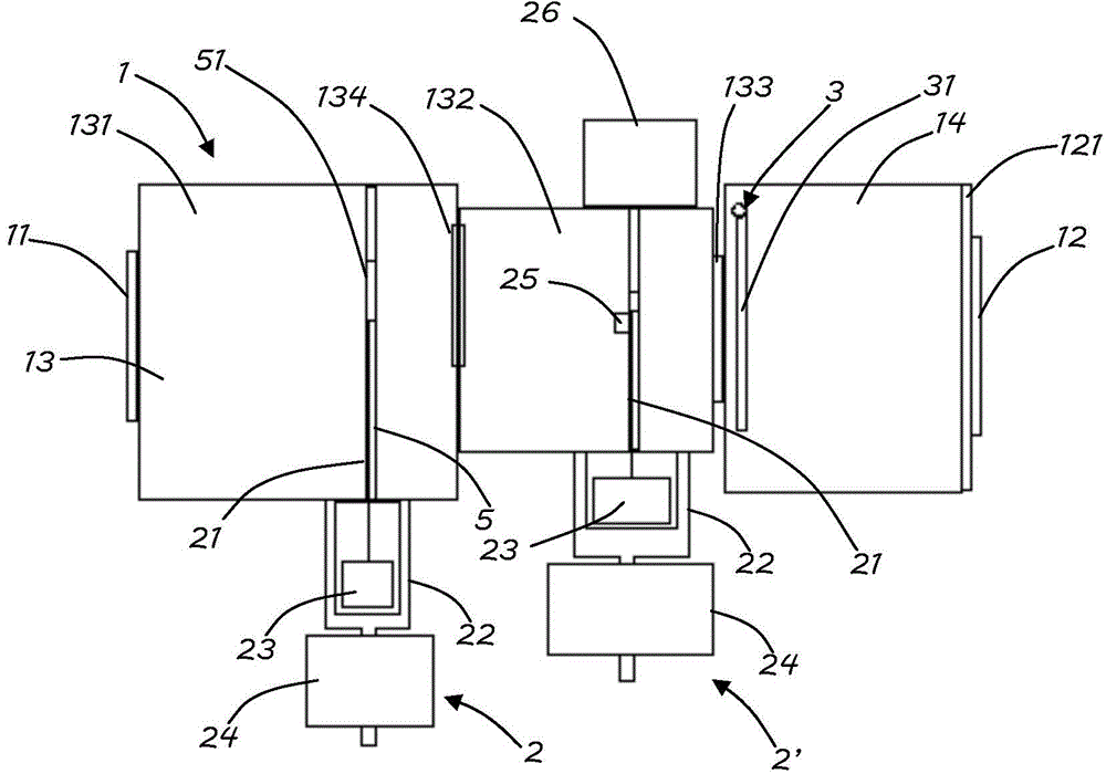
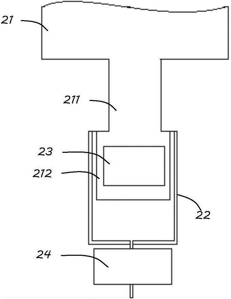
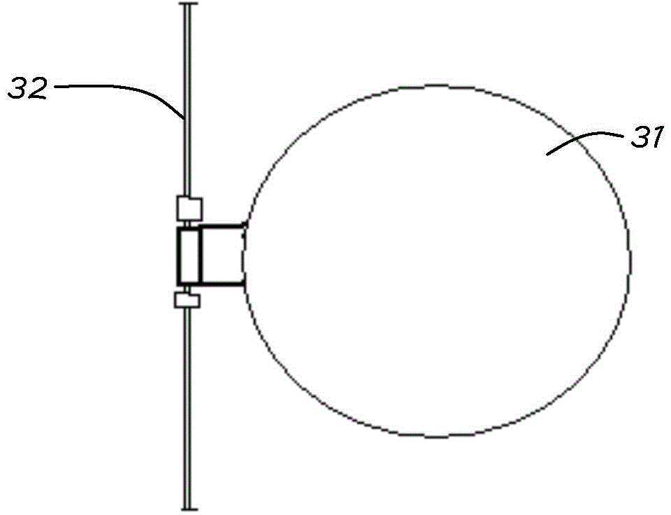
[0044] see figure 1 , figure 2 , a water mist flow control mechanism according to Embodiment 1 of the present invention, comprising a housing 1, an electronic control unit (not shown in the figure), a first valve 2, a second valve 2' and a signal acquisition mechanism 3; The housing 1 is used to form a water mist flow channel; the first valve 2 and the second valve 2' are both arranged in the housing 1, and are used to control the flow of water mist passing through; the signal acquisition mechanism 3 is used to detect the housing 1 The size of the internal air flow; the electronic control unit is used to control the opening of the valve 2 according to the size of the air flow detected by the signal acquisition mechanism 3 .

[0045] The housing 1 is separated to form a valve chamber 13 and a signal acquisition chamber 14; in this embodiment, the signal acquisition chambe...


PUM


Abstract

The invention discloses an internal combustion engine water mist flow control mechanism, a water combustion-supporting system and a control method of the water combustion-supporting system. The internal combustion engine water mist flow control mechanism comprises a shell, at least one valve, a signal acquisition mechanism and an electronic control unit, wherein the shell is used for forming a water mist flow channel, the valves are arranged in the shell and used for controlling the water mist flow passing through the shell, the signal acquisition mechanism is used for detecting the magnitude of the mist flow in the shell, and the electronic control unit is used for controlling the opening degrees of the valves according to the mist flow magnitude detected by the signal acquisition mechanism. By means of the internal combustion engine water mist flow control mechanism, the water combustion-supporting system and the control method of the water combustion-supporting system, control over water throughput can be achieved, and efficient and stable operation of a water combustion-supporting engine is guaranteed.

Description

technical field [0001] The invention relates to the field of internal combustion engines, in particular to a water mist flow control mechanism for an internal combustion engine, a water combustion-supporting system and a control method thereof. Background technique [0002] For those skilled in the art, adding an appropriate amount of water or other forms of water, such as mist, to the burning internal combustion engine (vehicle and ship engine) can reduce the pollution generated when the engine burns, reduce fuel consumption, and achieve the effect of water combustion . However, the effect of this method is not stable in actual use, sometimes good and sometimes bad, the overall effect is not obvious, and even fuel consumption increases, so no related products have entered the market at present. After testing, for a conventional engine that is only connected to a water mist generator, the engine can reduce fuel consumption and carbon dioxide emissions by about 12% under sta...

Claims


Application Information

Patent Timeline
Patent Type & Authority Applications(China)
IPC IPC(8): F02D19/12
CPCY02T10/12
Inventor 陶华陶克克
Owner 陶华
Why Eureka
Try Eureka