Exhaust gas recirculation apparatus of engine with supercharger

A technology of exhaust gas recirculation and supercharger, which is applied in the direction of machine/engine, engine components, engine control, etc.

Active Publication Date: 2015-03-25
AISAN IND CO LTD
View PDF9 Cites 14 Cited by
  • Summary
  • Abstract
  • Description
  • Claims
  • Application Information

AI Technical Summary

Problems solved by technology

In this EGR device, in order to prevent corrosion caused by condensed water generated inside the EGR passage whi...

Method used


Image

  • Exhaust gas recirculation apparatus of engine with supercharger
  • Exhaust gas recirculation apparatus of engine with supercharger
  • Exhaust gas recirculation apparatus of engine with supercharger

Examples


no. 1 Embodiment approach

[0071] Hereinafter, a first embodiment embodying an exhaust gas recirculation device for an engine with a supercharger according to the present invention will be described in detail with reference to the drawings.

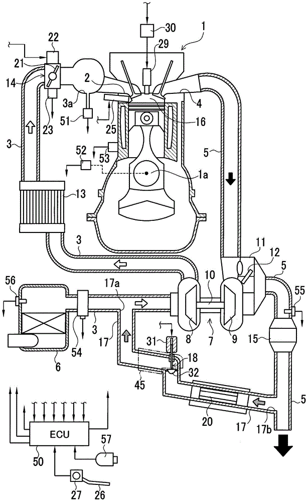
[0072] figure 1 A gasoline engine system including an exhaust gas recirculation device (EGR device) of an engine with a supercharger according to this embodiment is shown by a schematic configuration diagram. The engine system includes a reciprocating engine 1 . The intake port 2 of the engine 1 is connected to the intake passage 3 , and the exhaust port 4 is connected to the exhaust passage 5 . An air filter 6 is provided at the inlet of the intake passage 3 . On the intake passage 3 downstream of the air filter 6, a supercharger 7 is provided, and the supercharger 7 is used to make the intake air in the intake passage 3 between the intake passage 3 and the exhaust passage 5 Boost.

[0073] The supercharger 7 includes a compressor 8 arranged in the intake pas...

no. 2 Embodiment approach

[0106] Next, a second embodiment embodying an exhaust gas recirculation device for an engine with a supercharger according to the present invention will be described in detail with reference to the drawings.

[0107] In addition, in each embodiment described below, the same code|symbol is attached|subjected to the structural element equivalent to the said 1st Embodiment, and description is abbreviate|omitted, and it demonstrates centering on a difference.

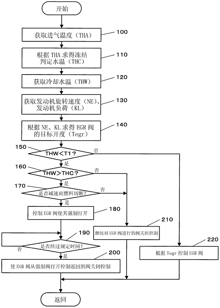
[0108] This embodiment differs from the configuration of the first embodiment in terms of the processing content of the condensed water discharge control. Figure 5 An example of the processing content of the condensed water discharge control of this embodiment is shown by the flowchart in FIG. exist Figure 5 In the flow chart of the image 3 The flow diagrams are different: except for image 3 In addition to the processing of the flowchart, the processing of step 165 is provided between step 160 and step 170, the proce...

no. 3 Embodiment approach

[0116] Next, a third embodiment embodying an exhaust gas recirculation device for an engine with a supercharger according to the present invention will be described in detail with reference to the drawings.

[0117] This embodiment differs from the configuration of the second embodiment in terms of the processing content of the condensed water discharge control. Figure 6 An example of the processing content of the condensed water discharge control of this embodiment is shown by the flowchart in FIG. exist Figure 6 In the flowchart of Figure 5 The processing of the flow chart is similar in that the processing of step 135 is provided instead of the processing of step 130, and the processing of steps 250 and 260 is newly provided. Figure 5 The flow chart is different.

[0118] After switching the processing to this routine and executing the processing of steps 100 to 120, in step 135, the ECU 50 obtains the engine rotational speed NE, Engine load KL and intake gas Ga.

...


PUM


Abstract

An exhaust gas recirculation apparatus of an engine with a supercharger, which prevents retention of a large amount of condensed water at the downstream side of an EGR valve, with the condensed water being generated by EGR gas leaked to the downstream side of the EGR valve during full closing of the EGR valve, is provided by the invention. The engine (1) is provided with the supercharger (7) and a low pressure loop EGR apparatus, wherein an electronic control unit (ECU) (50) controls the EGR valve (18) to be fully closed when a detected operating condition is a predetermined operating condition. An outlet (17a) of an EGR passage (17) is located at a higher position than an inlet (17b) in a vertical direction to allow condensed water to flow downward from downstream to upstream of the EGR valve (18) and flow downward through the EGR passage (17) to an exhaust passage (3). When the EGR valve (18) has to be controlled to be fully closed, to discharge the condensed water from a downstream side of the EGR valve (18), the ECU (50) forcibly opens the EGR valve (18) when a predetermined discharge condition is established.

Description

technical field [0001] The present invention relates to an engine including a supercharger, and relates to an exhaust gas recirculation device for an engine with a supercharger, which causes a part of the exhaust gas of the engine to flow into an intake passage as exhaust gas recirculation gas and recirculate the engine. Background technique [0002] Conventionally, for example, an Exhaust Gas Recirculation (EGR) device of an automobile engine guides part of the combusted exhaust gas discharged from the combustion chamber of the engine to the exhaust passage as EGR gas to the intake passage through the EGR passage. , so that it mixes with the intake air flowing in the intake passage and returns to the combustion chamber. The EGR gas flowing in the EGR passage is regulated by the EGR valve provided in the EGR passage. This EGR can mainly reduce nitrogen oxides (NOx) in exhaust gas, and improve fuel efficiency at the time of engine partial load. [0003] The exhaust of the e...

Claims


Application Information

Patent Timeline
IPC IPC(8): F02M25/07F02D41/04
CPCF02B29/0468F02M26/15F02M26/22Y02T10/12F02M26/06F02M26/50
Inventor 吉冈卫中村健英
Owner AISAN IND CO LTD
Why Eureka
Try Eureka