Hydraulic system for thread roller

A technology of hydraulic system and thread rolling machine, which is applied in the directions of fluid pressure actuating system components, mechanical equipment, fluid pressure actuating devices, etc., can solve the problems of unstable size, large error, low work efficiency, etc.

Inactive Publication Date: 2015-03-25
GUIZHOU JINGLI HANGTAI TECH
View PDF17 Cites 1 Cited by
  • Summary
  • Abstract
  • Description
  • Claims
  • Application Information

AI Technical Summary

Problems solved by technology

This type of machine tool often encounters dimensional instability and large errors when processing external threads. Wh...

Method used


Image

  • Hydraulic system for thread roller
  • Hydraulic system for thread roller
  • Hydraulic system for thread roller

Examples


Embodiment Construction

[0011] The present invention will be described in detail below in conjunction with the accompanying drawings.

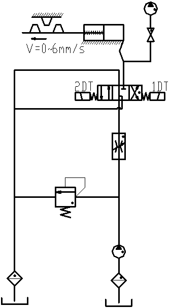
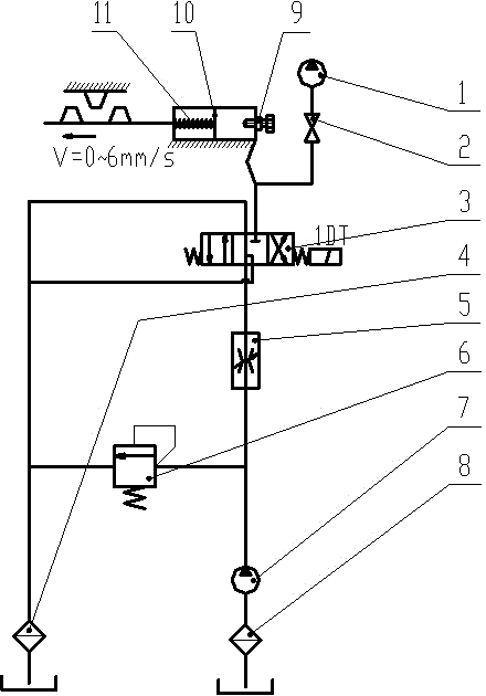
[0012] The thread rolling machine is a very common machine tool used in the machining industry. The following takes the ZA28-12.5 thread rolling machine as an example to introduce. The working principle of the ZA28-12.5 thread rolling machine is as follows:

[0013] Such as figure 1 As shown, after the machine tool is started, the three-position four-way reversing valve (1DT) is controlled by the rolling time relay. The hydraulic oil enters the oil cylinder through the oil pipe to move the piston forward to the front dead center, and the pressure is kept until the adjustable time is cut off. After the processing step is completed, another contact point of the rolling time relay controls the reversing valve (2DT) to work, so that the hydraulic oil pressure relief piston moves backwards to the travel switch disconnected by the reaction force of the return spring, and ...


PUM


Abstract

The invention relates to a hydraulic system for a thread roller. The hydraulic system mainly comprises a pressure meter, a pressure meter switch, a two-position four-way reversing valve, an oil return pipeline oil filter, a precision oil economizing valve, a pilot overflow valve, a vane pump, an oil suction port filter, an idle running adjustable mechanism, a piston and a spring. By means of the two-position four-way reversing valve of the hydraulic system, all hydraulic oil in an oil cylinder flows back to enable the piston to smoothly return to a rear stop point under the condition that 1DT loses power, and the control of the position limit switch over a 2DT is eliminated at the same time. The rear stop point adjustable mechanism is additionally arranged at the rear end of the oil cylinder, so that the position of the rear stop point where the piston returns is adjustable, and the idle running distance is reduced. The idle running adjustable mechanism is composed of a large nut, a small nut, a flat key, a handle and a screw. The handle is fixedly connected with the screw through the small nut and the flat key, and the large end of the screw is sleeved with the large nut. The hydraulic system for the thread roller is improved on the basis of an existing hydraulic system for the thread roller, the machining size is stable after the improvement, and the working efficiency is also greatly improved.

Description

technical field [0001] The invention belongs to the field of mechanical processing, in particular to a hydraulic system of a thread rolling machine. Background technique [0002] In the machining industry, the thread rolling machine is a machine tool for various purposes such as rolling various ordinary precision external threads and screw rods, small modulus worms, involute splines, small modulus helical gears, oil grooves, and knurls. This type of machine tool often encounters dimensional instability and large errors when processing external threads. When processing large-scale products, waste products are mixed in, causing a lot of work for inspection and low work efficiency. Contents of the invention [0003] The purpose of the invention is to improve the existing hydraulic system of the thread rolling machine so that it can not only ensure the stability of the processing size, but also improve the working efficiency. [0004] A thread rolling machine hydraulic system...

Claims


Application Information

Patent Timeline
IPC IPC(8): F15B11/02F15B21/04
CPCF15B13/044F15B13/0424F15B15/24F15B21/041
Inventor 柯平叶江华陈春旭
Owner GUIZHOU JINGLI HANGTAI TECH
Why Eureka
Try Eureka