Dual-Fuel Burning Gas Turbine Combustor

A technology for gas turbines and burners, applied in the directions of burners, combustion chambers, combustion methods, etc., can solve the problems of excessive thermal stress and leakage of welding parts, and achieve the effect of suppressing thermal shrinkage

Active Publication Date: 2015-03-25
MITSUBISHI POWER LTD
View PDF6 Cites 14 Cited by
  • Summary
  • Abstract
  • Description
  • Claims
  • Application Information

AI Technical Summary

Problems solved by technology

Therefore, since there is a temperature difference between the combustion air and the gas fuel, the O-ring cannot cope with the thermal deformation caused by the temperature difference when the gas fuel is supplied, and there is a possibility of leakage to the outside.
[0013] In the case of installing a single-tube sleeve instead of the O-ring, there is also a method of welding the sleeve to the end cover and the premixed burner so that the gaseous fuel does not leak to the outside. However, in the case of welding the sleeve, there are Possibility of excessive thermal stress on the welded part due to thermal shrinkage of the single-tube sleeve due to severe temperature changes on the sleeve

Method used


Image

  • Dual-Fuel Burning Gas Turbine Combustor
  • Dual-Fuel Burning Gas Turbine Combustor
  • Dual-Fuel Burning Gas Turbine Combustor

Examples


Embodiment 1

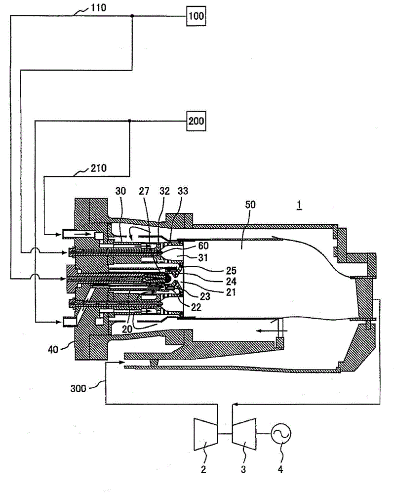
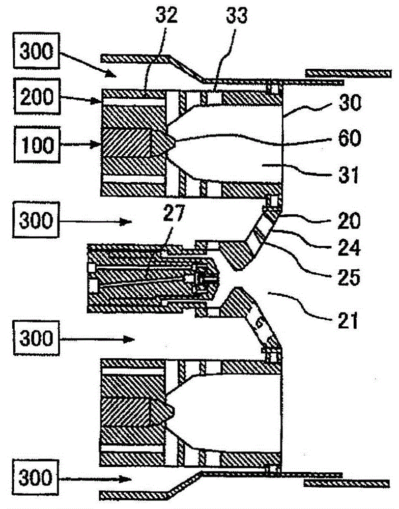
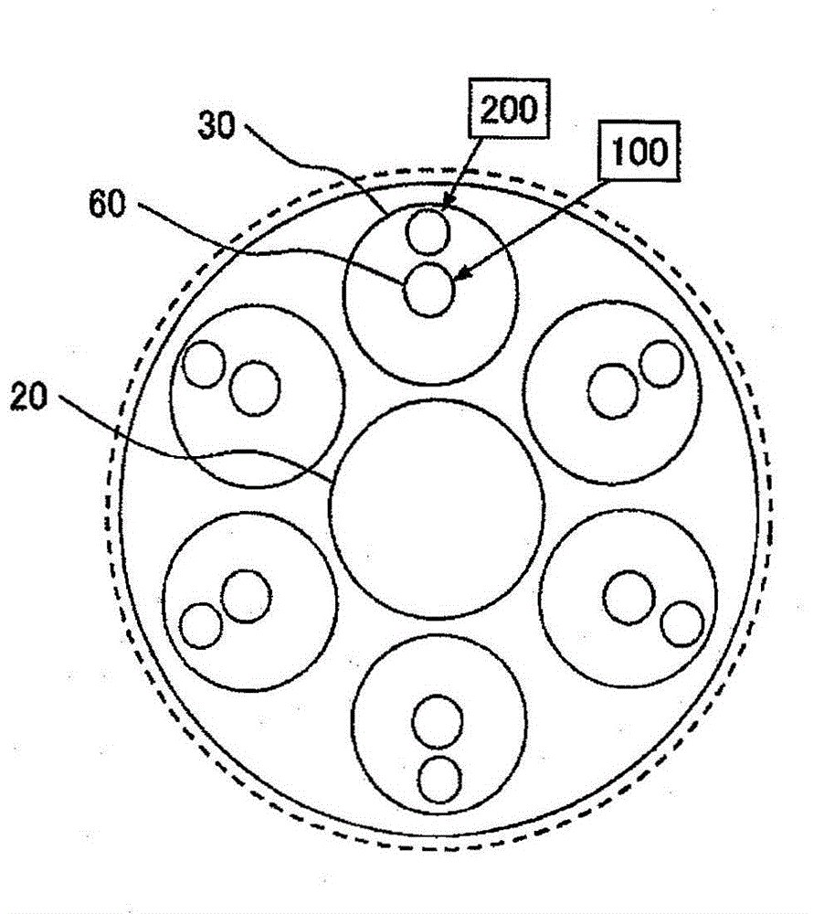
[0027] refer to Figure 1 ~ Figure 4 A dual fuel combustion gas turbine combustor using gas fuel and liquid fuel as fuel according to a first embodiment of the present invention will be described.

[0028] exist figure 1 And in the dual fuel combustion gas turbine combustor 1 using gaseous fuel and liquid fuel as fuel in the first embodiment of the present invention shown in FIG. 2 , the dual fuel combustion gas turbine combustor 1 of the present embodiment One diffusion burner 20 for injecting liquid fuel 100 and gaseous fuel 200 into the combustion chamber 50 for combustion is arranged on the central side in the axial direction of 1, and a plurality of premixing burners 30 are arranged on the outer peripheral side of the diffusion burner 20, For example, six premix burners 30 are respectively arranged on the outer peripheral side of the diffuser burner 20 at a distance from each other, and the liquid fuel 100 and the gas fuel 200 are injected into the combustion chamber 50 ...

Embodiment 2

[0077] Next refer to Figure 5 A dual fuel combustion gas turbine combustor using gas fuel and liquid fuel as fuel according to a second embodiment of the present invention will be described.

[0078] because Figure 5 The dual-fuel incineration gas turbine combustor 1 using gaseous fuel and liquid fuel as fuel of the present embodiment shown in FIG. Figure 1 ~ Figure 4 The basic structure of the dual-fuel combustion gas turbine combustor using gaseous fuel and liquid fuel as fuel in the first embodiment shown is the same, so the description common to both will be omitted below, and only the different structures will be described.

[0079] exist Figure 5 In the dual-fuel combustion gas turbine combustor 1 of the present embodiment shown, as far as the double-pipe sleeve 80 provided relative to the end cover 40 and the premixing burner 30 is concerned, the inner side sleeve of the above-mentioned double-pipe sleeve 80 is constituted. 81 abuts against the upstream side end ...


PUM


Abstract

A dual-fuel burning gas turbine combustor having a diffusive combustion burner to burn a liquid fuel and a gaseous fuel placed at the axis of the gas turbine combustor and a plurality of pre-mixing combustion burners to burn a liquid fuel and a gaseous fuel placed on an outer circumferential side of the diffusive combustion burner, each pre-mixing combustion burner having a liquid fuel nozzle, a plurality of gaseous fuel spray holes, a plurality of air holes, and a pre-mixing chamber to mix gaseous fuel and air, wherein each pre-mixing combustion burner has a double pipe sleeve at a connected portion between end cover and the pre-mixing combustion burner, and the double pipe sleeve has an inner sleeve having a gaseous fuel flow path, an outer sleeve positioned on an outer circumferential side of the inner sleeve, and a circular spacing formed between the inner sleeve and the outer sleeve.

Description

technical field [0001] The present invention relates to a gas turbine combustor, in particular to a gas turbine combustor in the form of a composite burner arranged with a plurality of burners, and a dual fuel combustion gas turbine combustor corresponding to both liquid fuel and gas fuel. Background technique [0002] In the power generation business in recent years, the demand for various fuels such as liquid fuels, which are relatively easy to supply, has increased due to the pressing demand for electric power, and gas turbine power generation equipment using burners for liquid fuels has been expected. [0003] As a gas turbine combustor, there is a gas turbine combustor employing a pre-evaporative pre-mixed combustion method in which liquid fuel and air are pre-mixed and combusted from the viewpoint of environmental protection. [0004] JP-A-2007-327338 and JP-A-2003-148734 disclose technologies related to dual fuel combustion gas turbine combustors compatible with both ...

Claims


Application Information

Patent Timeline
Patent Type & Authority Applications(China)
IPC IPC(8): F23R3/50
CPCF23D2211/00F23D2900/00008F23R3/286F23R3/36F23R3/283F23R3/30F23R3/32F23R3/34F23R2900/00002
Inventor 五十岚祥太高桥宏和
Owner MITSUBISHI POWER LTD
Why Eureka
Try Eureka