
Separator for non-aqueous electrolyte secondary battery and manufacturing method thereof

a technology of non-aqueous electrolyte and secondary batteries, which is applied in the manufacture of batteries, cell components, final products, etc., can solve the problems of excessive energy that causes the substrate layer to shrink, peeling of the layer, and short circuit generation, so as to achieve smooth movement, increase the heat resistance layer, and improve the effect of peel strength

Active Publication Date: 2016-10-20
TOYOTA JIDOSHA KK
View PDF1 Cites 8 Cited by
  • Summary
  • Abstract
  • Description
  • Claims
  • Application Information

AI Technical Summary

Benefits of technology

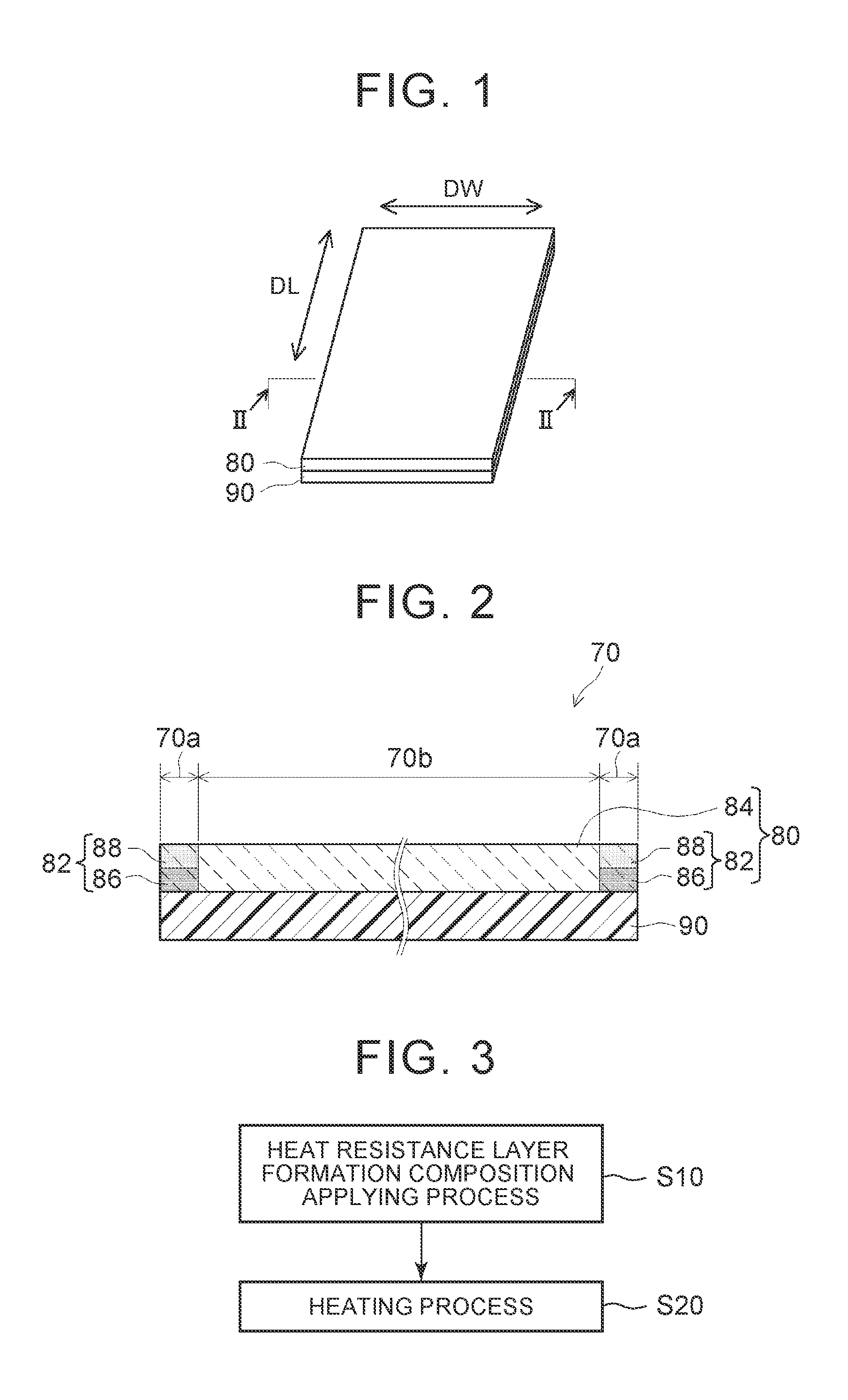
The invention provides a separator for non-aqueous electrolyte secondary batteries that prevents thermal shrinkage and reduces battery resistance. This is achieved by increasing the peel strength between the substrate layer and the heat resistance layer at the end portion in the width direction perpendicular to the longitudinal direction of the substrate layer. By increasing the amount of binder in the heat resistance layer and heating the heat resistance layer formation composition, the binder moves and concentrates in the portion with a relatively high temperature, resulting in a separator with a high amount of binder in the end portion and a reduced amount of binder in the center portion in the width direction. This prevents internal short-circuits and reduces battery resistance. The non-aqueous electrolyte secondary battery using this separator has reduced battery resistance and high stability.

Problems solved by technology

For example, when the inside of the battery is overheated to the softening point of the resin forming the separator or higher and the separator shrinks due to the heat, there is concern that a short-circuit may be generated due to an insufficient coating area of the separator over the electrodes, the breakage of the separator, or the like.
However, for example, in a case where the battery is exposed to harsher conditions (for example, exposure to an environment at a higher temperature, or exposure to an environment at a high temperature for a long period of time), the energy that causes the substrate layer to shrink becomes excessive, and there may be cases where the heat resistance layer peels off from the substrate layer.
That is, although the heat resistance of the separator can be enhanced by forming the heat resistance layer on the surface of the substrate layer, when the heat resistance layer peels off from the substrate layer, it becomes difficult to suppress the shrinkage (thermal shrinkage) of the separator at a position where the heat resistance layer peels off, and there may be cases where the function of preventing short-circuits is not sufficiently exhibited.

Method used


Image

  • Separator for non-aqueous electrolyte secondary battery and manufacturing method thereof
  • Separator for non-aqueous electrolyte secondary battery and manufacturing method thereof
  • Separator for non-aqueous electrolyte secondary battery and manufacturing method thereof

Examples


example 1

[0086]The separator according to Example 1 was produced as follows. First, alumina as the inorganic filler and the acrylic resin as the binder were mixed with ion-exchange water at a mass ratio of inorganic filler:binder=96:4, thereby preparing a slurry-like (paste-like) heat resistance layer formation composition. The concentration (in terms of NV, that is, in terms of solid content) of the binder contained in the total solid content of the heat resistance layer formation composition is shown in the row of “binder concentration (mass %)” of Table 1. Thereafter, the heat resistance layer formation composition was applied to only one surface of the separator substrate. Here, the application of the heat resistance layer formation composition was performed using a gravure coater so that the heat resistance layer formation composition was applied to the entire surface of the separator substrate (one surface). Next, the heat resistance layer formation composition applied to both end port...

examples 4 , 5 , 10

Examples 4, 5, 10, and 11

[0088]Separators according to Examples 4, 5, 10, and 11 were produced according to the same process and materials as those of Example 2 except that the heating temperatures when both end portions in the width direction of the separators were heated from the separator substrate layer side were 80° C., 110° C., 50° C., and 70° C.

example 6

[0089]A separator according to Example 6 was produced according to the same process and materials as those of Example 1 except that the heat resistance layer formation composition applied to both end portions in the width direction of the substrate layer was not locally heated (that is, both end portions were regions with a width of 0 mm from the edge portions).


PUM


Abstract

A separator includes a substrate layer made of a resin and a heat resistance layer. The heat resistance layer contains heat-resistant fine particles and a binder. An amount of the binder contained per unit volume in the heat resistance layer positioned at an end portion in a width direction perpendicular to a longitudinal direction of the separator is higher than the amount of the binder contained per unit volume in the heat resistance layer (84) positioned at a center portion which includes the center in the width direction of the separator. In the heat resistance layer at the end portion, the amount of the binder contained per unit volume in a substrate layer side region is higher than the amount of the binder contained per unit volume in a surface region which includes a surface of the heat resistance layer.

Description

INCORPORATION BY REFERENCE[0001]The disclosure of Japanese Patent Application No. 2015-082403 filed on Apr. 14, 2015 including the specification, drawings and abstract is incorporated herein by reference in its entirety.BACKGROUND OF THE INVENTION[0002]1. Field of the Invention[0003]The invention relates to a separator for a non-aqueous electrolyte secondary battery, and a manufacturing method thereof.[0004]2. Description of Related Art[0005]A non-aqueous electrolyte secondary battery such as a lithium-ion secondary battery (lithium secondary battery) is lightweight and has high energy density compared to existing batteries, and has been used as a so-called portable power source for a personal computer (PC), a portable terminal, or the like, or a power source for driving a vehicle in recent years. Particularly, a lithium-ion secondary battery which achieves high energy density with a low weight is preferably used as a high-output power source for driving a vehicle such as an electri...

Claims


Application Information

Patent Timeline
IPC IPC(8): H01M2/16H01M10/0525H01M2/14H01M50/403H01M50/414H01M50/443H01M50/449
CPCH01M2/1686H01M2/145H01M2/1673H01M10/0525H01M2220/20H01M50/403H01M50/443H01M50/414H01M50/449H01M10/05H01M10/4235Y02E60/10Y02P70/50H01M50/46H01M50/489H01M50/463
Inventor KONDO, SHINPEIOYAMA, YUTAKAOCHIAI, AKIHIRO
Owner TOYOTA JIDOSHA KK
Learn More