
Time-frequency diagram processing method and system for mechanical equipment monitoring vibration signals

A technology of vibration signal and processing method, which is applied in the field of diagnosis and mechanical equipment fault monitoring, and can solve problems such as difficult real-time diagnosis of faults, inability to apply, long storage time of huge amounts of data, etc.

Active Publication Date: 2015-03-25
GUILIN UNIV OF ELECTRONIC TECH
View PDF7 Cites 30 Cited by
  • Summary
  • Abstract
  • Description
  • Claims
  • Application Information

AI Technical Summary

Problems solved by technology

When monitoring the condition of mechanical equipment for a long time, the data that needs to be stored will be extremely huge, and the long storage time of huge data will make it difficult to realize real-time diagnosis of faults
Therefore, this has become a bottleneck that seriously restricts the application of time-frequency analysis technology in mechanical equipment condition monitoring and real-time diagnosis
In addition, many excellent fault feature extraction methods based on time-frequency analysis cannot be applied due to the above-mentioned bottleneck restrictions, and can only stay at the theoretical level

Method used


Image

  • Time-frequency diagram processing method and system for mechanical equipment monitoring vibration signals
  • Time-frequency diagram processing method and system for mechanical equipment monitoring vibration signals
  • Time-frequency diagram processing method and system for mechanical equipment monitoring vibration signals

Examples


Embodiment Construction

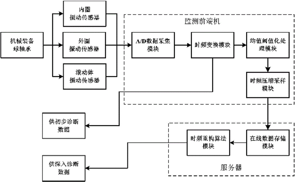
[0060] Embodiments of the time-frequency diagram processing method and system for monitoring vibration signals of the mechanical equipment are further described in detail below with reference to the accompanying drawings.

[0061] Embodiment of time-frequency map processing system for mechanical equipment monitoring vibration signal

[0062] Rolling bearings are key components in mechanical equipment. However, rolling bearings may be damaged due to various reasons during operation, such as improper assembly, poor lubrication, moisture and foreign matter intrusion, corrosion and overloading, etc., which may lead to premature failure of rolling bearings. Even if the installation, lubrication and maintenance are normal, after a period of operation, the rolling bearing will experience fatigue spalling, wear, pitting and other faults, resulting in failure to work normally.

[0063] The embodiment of the time-frequency diagram processing system for monitoring vibration signals of me...


PUM


Abstract

The invention discloses a time-frequency diagram processing method and system for mechanical equipment monitoring vibration signals. The time-frequency diagram processing method comprises the steps that firstly, linear or bilinear time-frequency transformation is carried out on collected mechanical equipment monitoring vibration signals to obtain a time-frequency diagram TFRs, and average threshold processing is carried out on the time-frequency diagram TFRs to obtain a sparse time-frequency diagram STFRs; secondly, time-frequency compression sampling is carried out on the STFRs in a random sampling mode to obtain a matrix M<STFR > with dimensionality being k times the dimensionality of an original matrix; thirdly, the parallel class FISTA proximal decomposition method is used for reconstructing an STFRs* through iterative computation. The time-frequency diagram processing system comprises a monitoring front-end machine and a server connected with the monitoring front-end machine. The monitoring front-end machine comprises an A / D data collection module, a time-frequency transformation module, an average thresholding module and a time-frequency compression sampling module and is connected with a vibration sensor. The server comprises an on-line data storage module and a reconstruction algorithm module. According to the time-frequency diagram processing method and system, the dimensionality of the reconstructed time-frequency diagram is greatly reduced, data storage and transmission are facilitated, and time-frequency analysis technology can be widely applied for mechanical equipment fault real-time quantitative analysis and diagnosis.

Description

technical field [0001] The invention belongs to the field of mechanical equipment fault monitoring and diagnosis, and in particular relates to a time-frequency diagram processing method and system for mechanical equipment monitoring vibration signals. Background technique [0002] Mechanical fault diagnosis is of great significance to improve the overall operational safety and reliability of equipment and to avoid unexpected shutdowns and vicious accidents. When machinery fails, the collected vibration signals are often non-stationary, non-Gaussian and nonlinear random signals. The analysis of such vibration signals mainly includes the Fourier transform spectrum analysis method. The premise of this method for signal analysis is to assume that the signal is stationary, so this method does not work in the time domain, especially for non-stationary signals. Analysis, since the signal analysis is performed on a global average, that is, any sudden change in the time axis, its sp...

Claims


Application Information

Patent Timeline
IPC IPC(8): G01M7/02G01H17/00G01H11/06G01H11/08
Inventor 王衍学蒋占四丁永彬孟令杰
Owner GUILIN UNIV OF ELECTRONIC TECH
Learn More