Insulation fault locating system and insulation monitoring system

A technology of insulation fault and locating system, applied in fault location, lamp test, emergency protection device with automatic disconnection, etc., to achieve the effect of fast measurement

Active Publication Date: 2015-03-25
BENDER SA
View PDF6 Cites 18 Cited by
  • Summary
  • Abstract
  • Description
  • Claims
  • Application Information

AI Technical Summary

Problems solved by technology

However, these solutions can only be reliably

Method used


Image

  • Insulation fault locating system and insulation monitoring system
  • Insulation fault locating system and insulation monitoring system
  • Insulation fault locating system and insulation monitoring system

Examples


Embodiment Construction

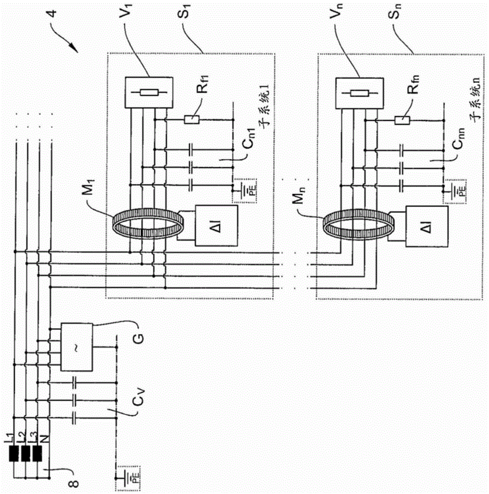
[0047] figure 1 Shows a system with n subsystems (subnetworks) S corresponding to the prior art in the art 1 ,...,S n Structure of a typical insulation fault locator for branch IT systems 4. As an example, the IT system 4 is configured with an outer conductor L 1 , L 2 , L 3 , a three-phase power network with a neutral conductor N and a protective earth wire PE. Effective conductor L 1 , L 2 , L 3 and N connect the power source 8 to a separate subsystem S via a branch line system 1 ,...,S n Each load in V 1 ,...,V n . At a central location, a test signal generator G for feeding in test signals is arranged in the main system. If subsystem S 1 ,...,S n appears to have a fault resistor R f1 ,...,R fn insulation fault, the fault subsystem S 1 ,...,S n The test signal in the differential current measurement device M 1 ,...,M n recorded and can subsequently be evaluated in the central evaluation unit.

[0048] The network configuration shown is also characteriz...


PUM


Abstract

The invention relates to an insulation fault locating system using branch-selective feeding and to a selective insulation monitoring system for a branched IT system composed of multiple subsystems. For insulation fault location, a differential current measuring device, a test signal generator and a blocking device are arranged in each subsystem. The insulation monitoring device additionally comprises a selective decoupling device arranged in each subsystem. Furthermore, the invention relates to a method for determining a cross impedance between two subsystems on the basis of the insulation monitoring system according to the invention.

Description

technical field [0001] The invention relates to an insulation fault location system for a branch IT system having a subsystem (subnetwork) and a differential current measuring device arranged in the subsystem for recording a differential current measuring signal. Furthermore, the invention includes an insulation monitoring system for monitoring insulation resistance in a branch IT system with subsystems and having the feature of an insulation fault location system, and relates to a method for determining A method of cross-connecting impedance between two subsystems. Background technique [0002] In order to ensure high availability and operational safety of the power supply and to guarantee personal safety in the operator's area of ​​the electrical installation, power supply networks in which the active components are separated from the ground potential are increasingly being used. In this type of power network known as IT system, the active conductor may present an insulat...

Claims


Application Information

Patent Timeline
IPC IPC(8): G01R31/08G01R27/18
CPCG01R27/18G01R31/08G01R31/14H02H3/334H02H7/26G01R19/0092G01R27/16G01R31/44
Inventor 迪特尔·黑克尔
Owner BENDER SA
Why Eureka
Try Eureka