
Terminal structure of metal oxide semiconductor field effect transistor and manufacturing method of terminal structure of metal oxide semiconductor field effect transistor

A technology of oxide semiconductors and field effect transistors, applied in semiconductor/solid-state device manufacturing, semiconductor devices, electrical components, etc., can solve problems such as large chip area, achieve optimal parameters, increase effective use area, and increase breakdown voltage Effect

Active Publication Date: 2015-03-25
深圳深爱半导体股份有限公司
View PDF4 Cites 4 Cited by
  • Summary
  • Abstract
  • Description
  • Claims
  • Application Information

AI Technical Summary

Problems solved by technology

[0003] At present, the terminal of most MOSFETs still adopts the voltage divider ring structure. The disadvantage of this structure is that it occupies a large chip area.

Method used


Image

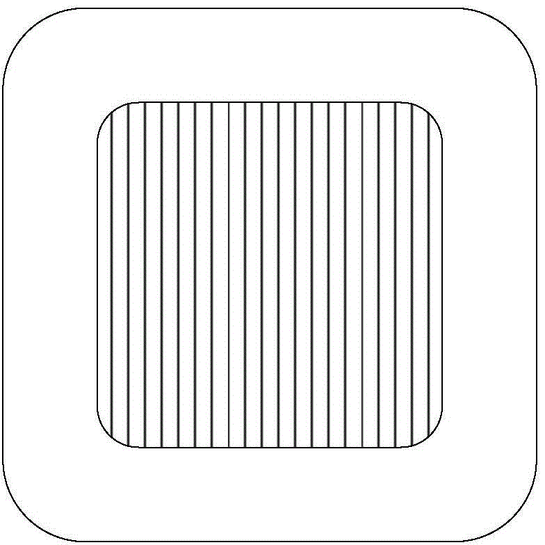
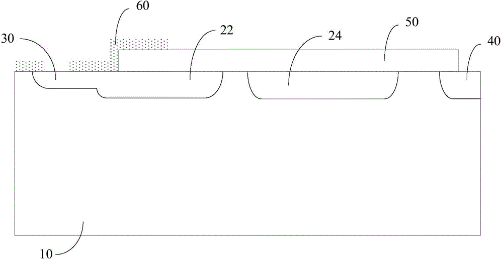
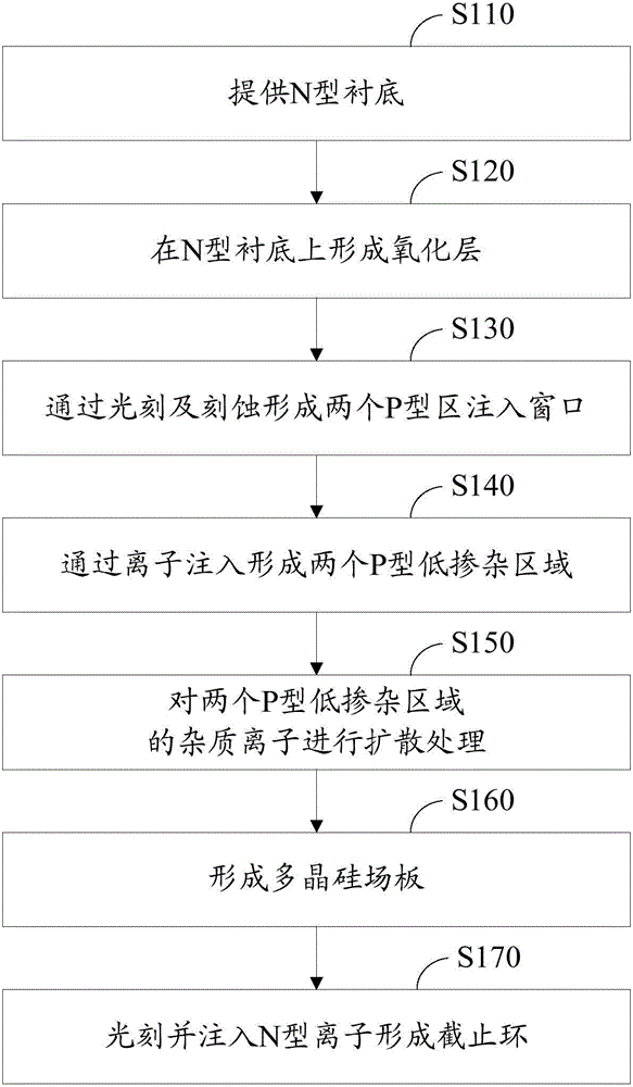
  • Terminal structure of metal oxide semiconductor field effect transistor and manufacturing method of terminal structure of metal oxide semiconductor field effect transistor
  • Terminal structure of metal oxide semiconductor field effect transistor and manufacturing method of terminal structure of metal oxide semiconductor field effect transistor
  • Terminal structure of metal oxide semiconductor field effect transistor and manufacturing method of terminal structure of metal oxide semiconductor field effect transistor

Examples


Embodiment Construction

[0021] In order to facilitate the understanding of the present invention, the present invention will be described more fully below with reference to the associated drawings. A preferred embodiment of the invention is shown in the drawings. However, the present invention can be embodied in many different forms and is not limited to the embodiments described herein. Rather, these embodiments are provided so that the disclosure of the present invention will be thorough and complete.

[0022] It should be noted that when an element is referred to as being “fixed” to another element, it can be directly on the other element or there can also be an intervening element. When an element is referred to as being "connected to" another element, it can be directly connected to the other element or intervening elements may also be present. The terms "vertical," "horizontal," "upper," "lower," "left," "right," and similar expressions are used herein for purposes of illustration only.

[0...


PUM


Abstract

The invention relates to a terminal structure of a metal oxide semiconductor field effect transistor (MOSFET). The terminal structure comprises an N-type cut-off ring and further comprises a first P-type low-doped region and a second P-type low-doped region, wherein the first P-type low-doped region and the second P-type low-doped region are formed between the cut-off ring and an active region through ion implantation, the implantation dose ranges from 1.5*10<11> / cm<2> to 2*10<13> / cm<2>, implantation energy ranges from 20 kilo electron volts to 80 kilo electron volts, the first P-type low-doped region is closer to the active region than the second P-type low-doped region, and the length of the first P-type low-doped region is smaller than that of the second P-type low-doped region. The invention further relates to a manufacturing method of the terminal structure of the MOSFET. The two P-type low-doped regions are adopted for reducing a surface electric field and increasing the breakdown voltage of the MOSFET, the terminal structure replaces a traditional terminal structure with a plurality of voltage dividing rings, the terminal size is greatly reduced, the effective use area of a chip is increased, and parameters of the chip are more excellent under the same area.

Description

technical field [0001] The invention relates to semiconductor technology, in particular to a terminal structure of a metal oxide semiconductor field effect transistor, and also to a manufacturing method of the terminal structure of a metal oxide semiconductor field effect transistor. Background technique [0002] The metal-oxide-semiconductor field-effect transistor (MOSFET) market competition is becoming more and more exciting, and all manufacturers are trying to reduce costs. The solutions adopted mainly include increasing the current density, increasing the effective use area of ​​the chip, and reducing the size of the terminal. [0003] At present, the terminals of most MOSFETs still use a voltage divider ring structure. The disadvantage of this structure is that it occupies a large chip area. Contents of the invention [0004] Based on this, it is necessary to provide a terminal structure of a metal oxide semiconductor field effect transistor with a smaller size. [...

Claims


Application Information

Patent Timeline
Patent Type & Authority Applications(China)
IPC IPC(8): H01L29/78H01L21/336H01L29/06
CPCH01L29/0684H01L29/66477H01L29/78
Inventor 李杰周大伟魏国栋刘玮汪德文
Owner 深圳深爱半导体股份有限公司
Learn More