Organic electroluminescent device and manufacturing method thereof
An electroluminescence device and luminescence technology, which is applied in the direction of organic light-emitting devices, organic light-emitting device structures, organic semiconductor devices, etc., can solve the problems of low light extraction performance, total reflection loss, etc., to improve the purity of light color and reduce holes Potential barrier, effect of improving injection efficiency
- Summary
- Abstract
- Description
- Claims
- Application Information
AI Technical Summary
Problems solved by technology
Method used
Image

Examples
Embodiment 1
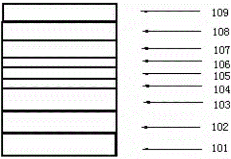
[0032] Such as figure 1 As shown, the organic electroluminescent device in this embodiment is a layered structure, and each layer is in turn:
[0033] Glass substrate 101 , anode layer 102 , ternary doped layer 103 , hole injection layer 104 , hole transport layer 105 , light emitting layer 106 , electron transport layer 107 , electron injection layer 108 and cathode layer 109 . The ternary doped layer 103 constitutes the heat dissipation layer. The structure of the organic electroluminescent device is glass substrate / ITO / Al:BCzVBi:MoO 3 / WO 3 / NPB / BCzVBi / TAZ / CsF / Ag, where the slash " / " indicates a layered structure, and the colon ":" indicates mutual doping. )
[0034] The above-mentioned organic electroluminescent device is prepared according to the following steps in sequence:
[0035] (1) Coating pretreatment
[0036] Take out the glass substrate 101 whose glass grade is N-LASF44, rinse it with distilled water and ethanol, and soak it in isopropanol for one night.
...
Embodiment 2
[0045] The organic electroluminescent device in this embodiment has a layered structure, and each layer is in turn: glass substrate, anode layer, ternary doped layer, hole injection layer, hole transport layer, light emitting layer, electron transport layer, electron injection layer and cathode layer.
[0046] Said and said ternary doped layer constitute said heat dissipation layer. The structure of the organic electroluminescent device is glass substrate / IZO / Ag:AND:WO 3 / V 2 o 5 / NPB / ADN / Bphen / Cs 2 CO 3 / Pt, where the slash " / " indicates a layered structure, and the colon ":" indicates mutual doping. The above-mentioned organic electroluminescent device is prepared according to the following steps in sequence:
[0047] (1) Coating pretreatment
[0048] Take out the glass substrate whose glass grade is N-LAF36, rinse it with distilled water and ethanol, and soak it in isopropanol for one night.
[0049] (2) Preparation of the anode layer
[0050] Place the glass subst...
Embodiment 3
[0056] The organic electroluminescent device in this embodiment is a layered structure, and each layer is sequentially:
[0057] A glass substrate, an anode layer, a ternary doped layer, a hole injection layer, a hole transport layer, a light emitting layer, an electron transport layer, an electron injection layer and a cathode layer. Said and said ternary doped layer constitute said heat dissipation layer. The structure of the organic electroluminescent device is glass substrate / AZO / Pt:Alq 3 :V 2 o 5 / MoO 3 / TCTA / Alq 3 / TAZ / LiF / Au, where the slash " / " indicates a layered structure, and the colon ":" indicates mutual doping. The above-mentioned organic electroluminescent device is prepared according to the following steps in sequence:
[0058] (1) Coating pretreatment
[0059] Take out the glass substrate whose glass grade is N-LASF31A, rinse it with distilled water and ethanol, and soak it in isopropanol for one night.
[0060] (2) Preparation of the anode layer
[0...
PUM
 Abstract
Description
Claims
Application Information
 - R&D
- Intellectual Property
- Life Sciences
- Materials
- Tech Scout
- Unparalleled Data Quality
- Higher Quality Content
- 60% Fewer Hallucinations
Browse by: Latest US Patents, China's latest patents, Technical Efficacy Thesaurus, Application Domain, Technology Topic, Popular Technical Reports.
© 2025 PatSnap. All rights reserved.Legal|Privacy policy|Modern Slavery Act Transparency Statement|Sitemap|About US| Contact US: help@patsnap.com