
A Single Light Source Parallel Rotary Ventilation Laser Machining Spindle System

A technology of laser processing and single light source

Active Publication Date: 2016-01-20
JIANGSU UNIV
View PDF11 Cites 0 Cited by
  • Summary
  • Abstract
  • Description
  • Claims
  • Application Information

AI Technical Summary

Problems solved by technology

[0005] Aiming at the problems of low laser processing efficiency and difficulty in consistent processing quality on the surface of inner holes of parts with holes, the present invention proposes a single-light source parallel rotary ventilation laser processing spindle system, which is especially suitable for multi-cylinder engine cylinder hole surfaces with small hole spacing. laser processing

Method used


Image

  • A Single Light Source Parallel Rotary Ventilation Laser Machining Spindle System
  • A Single Light Source Parallel Rotary Ventilation Laser Machining Spindle System
  • A Single Light Source Parallel Rotary Ventilation Laser Machining Spindle System

Examples


Embodiment 1

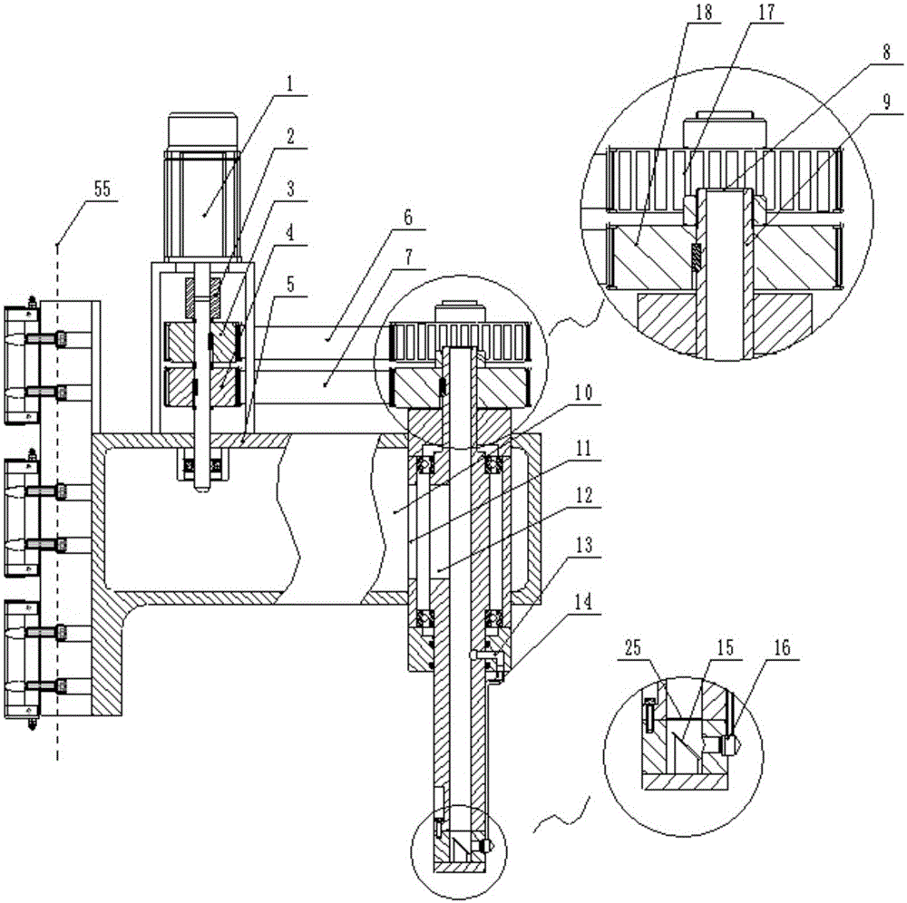
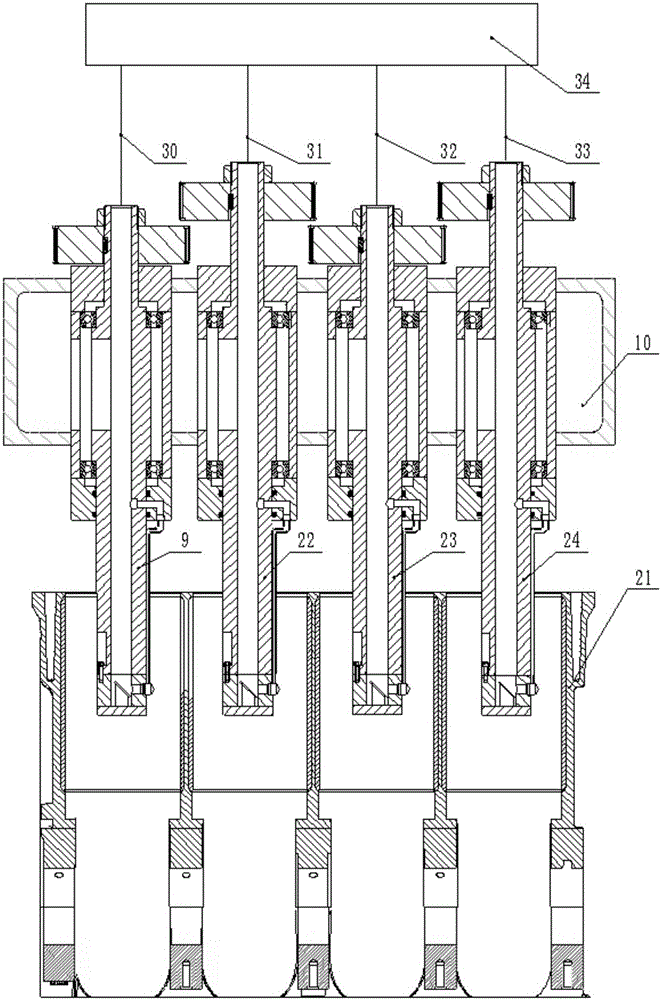
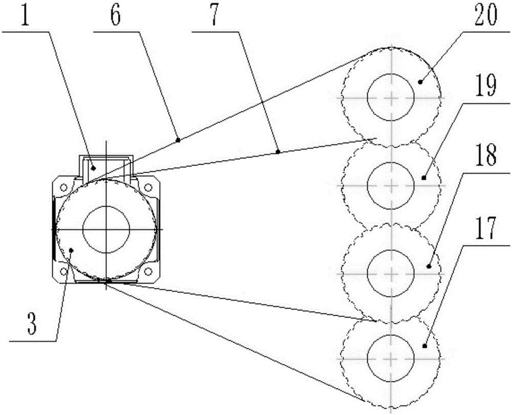
[0032] Embodiment one, such as Figure 1-4 As shown, the processing object of the present invention is an in-line 4-cylinder engine block 21, and the axes of each cylinder hole are arranged in the same plane and equidistant. Correspondingly, the present invention has a laser processing spindle A9, a laser processing spindle B22, a laser processing spindle C23 and a laser processing spindle D24; the axis of the laser processing spindle A9 coincides with the cylinder bore A, and the axis of the laser processing spindle B22 coincides with the cylinder bore B, The axis of the laser machining spindle C23 coincides with the cylinder bore C, and the axis of the laser machining spindle D24 coincides with the cylinder bore D. The laser source 34 outputs the laser beam A50, the laser beam B51, the laser beam C52 and the laser beam D53; the full reflection sheet D42 reflects the laser beam A50 into a vertical laser beam A30, and the vertical laser beam A30 is incident on the laser proces...

Embodiment 2

[0039] Example two such as Figure 5 shown.

[0040] The difference between Embodiment 2 and Embodiment 1 is that in Embodiment 2, laser micromachining is completed on the surface of the cylinder bore. The laser micromachining specifically refers to etching pits or grooves on the surface of the cylinder bore by laser. The diameter of the pit shape is 10 μm-1 mm; the width of the groove is 10 μm-0.5 mm, and the length is greater than 0.5 mm. In the laser micromachining process, the rotating speed of the spindle motor is 0-1800 rpm. In order to make the working condition of the spindle motor 1 close to its rated working condition and realize the deceleration transmission, the deceleration ratio is 3:1, and the spindle motor 1 The small motor pulley 60 is assembled at the motion output end of the laser processing main shaft A9, the laser processing main shaft B22, the laser processing main shaft C23 and the laser processing main shaft D24 end are assembled with a large main shaf...


PUM

PropertyMeasurementUnit
sizeaaaaaaaaaa
lengthaaaaaaaaaa
diameteraaaaaaaaaa

Abstract

The invention discloses a single-light-source parallel rotating and ventilating laser processing spindle system which is applicable to the laser processing of surfaces of inner pores of porous parts. According to the technical scheme, the single-light-source parallel rotating and ventilating laser processing spindle system is that laser processing spindles are grouped, wherein transmission systems of the laser processing spindles in each group are arranged by layers; each laser processing spindle is driven to rotate through a motor; the energy of a laser source is divided and respectively introduced into each processing spindle through an external light path; auxiliary air is charged into each spindle and then is output together with laser by a coaxial manner. According to the single-light-source parallel rotating and ventilating laser processing spindle system, the laser output and the rotating of the spindles are under one source, so that the processing quality caused by the fluctuation of laser power and the mechanical vibration can be avoided being unstable; the beneficial effects achieved are that the processing efficiency is raised in multiples, the structure of the system is compact, and the stability of the system is improved; the system is particularly suitable for laser processing of surfaces of cylinder pores with small spacing of a multi-cylinder engine.

Description

technical field [0001] The invention relates to a single-light-source parallel rotating ventilating laser machining spindle system, which belongs to the special machining field of mechanical manufacturing. Background technique [0002] Laser processing has the advantages of no stress, no contact, easy focusing, energy saving and high efficiency, and is widely used in the machinery manufacturing industry. The existing laser processing technology for the surface of the inner hole mainly includes: 1. Laser quenching, which uses the thermal effect of the laser to harden the surface of the inner hole, greatly improving the hardness and wear resistance of the inner hole surface; 2. Laser micro-texture, processing the inner hole surface with micron Standard pits or grooves reduce the coefficient of friction between friction pairs; 3. Laser cladding, directional repair of local wear or failure areas on the surface of the inner hole. [0003] Inner hole laser processing equipment ha...

Claims


Application Information

Patent Timeline
Patent Type & Authority Patents(China)
IPC IPC(8): B23K26/00B23K26/08B23K26/067B23K26/70
CPCB23K26/0643B23K26/0648B23K26/14B23K26/36
Inventor 康正阳符永宏王林森陈天阳符号纪敬虎
Owner JIANGSU UNIV
Learn More