Automatic insertion pin grinding method and grinding machine

A technology of grinding machine and grinding mechanism, which is applied to vibration conveyors, grinding machines, conveyors, etc., can solve problems such as unfavorable product quality control, uneven pin grinding quality, and unfavorable mass production. performance, optimization of processing processes and procedures, and the effect of stable product quality

Active Publication Date: 2015-04-01
浦北瀛通智能电子有限公司
View PDF7 Cites 11 Cited by
  • Summary
  • Abstract
  • Description
  • Claims
  • Application Information

AI Technical Summary

Problems solved by technology

[0003] The traditional grinding process of electrical connection pins for electronic products is mostly manual grinding, which is inefficient and has great instability, resulting in uneven grinding quality of the pins
Even if the corresponding auxiliary equipment is used in the pin grinding process, it can only achieve semi-automation at most, with high manual dependence, which is not conducive to mass production, and is not conducive to the stable control of product quality

Method used


Image

  • Automatic insertion pin grinding method and grinding machine
  • Automatic insertion pin grinding method and grinding machine
  • Automatic insertion pin grinding method and grinding machine

Examples


Embodiment Construction

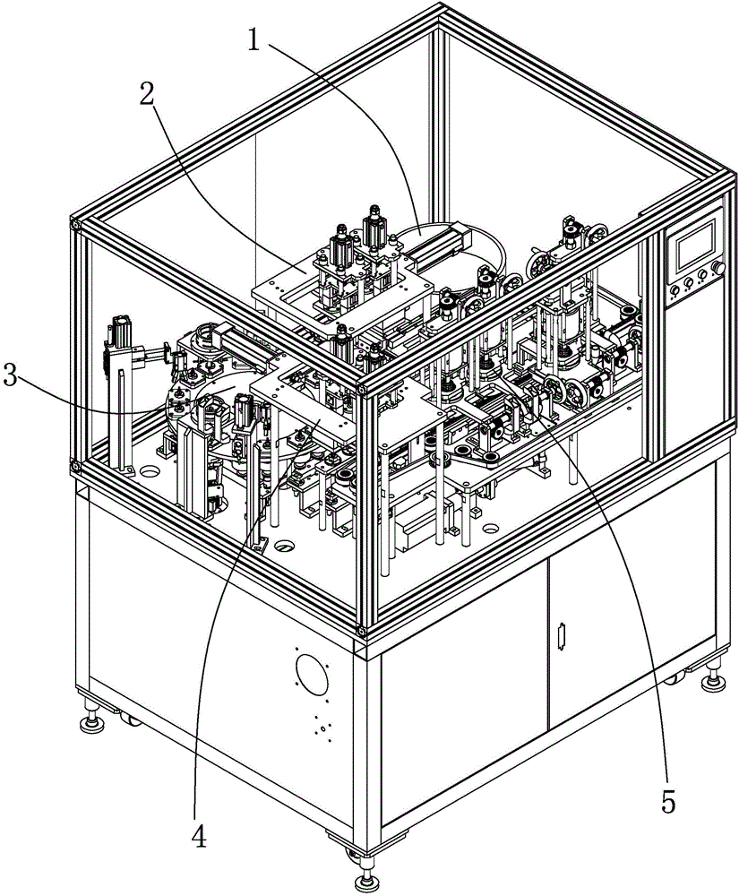
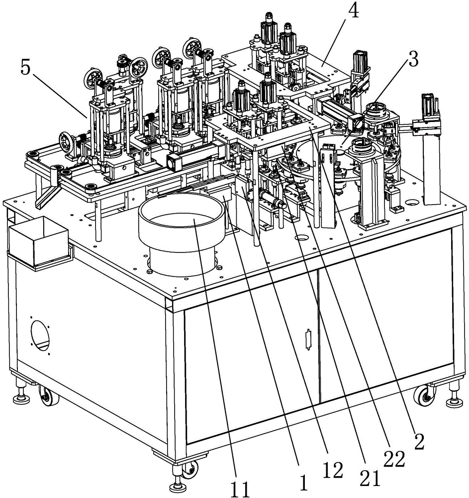
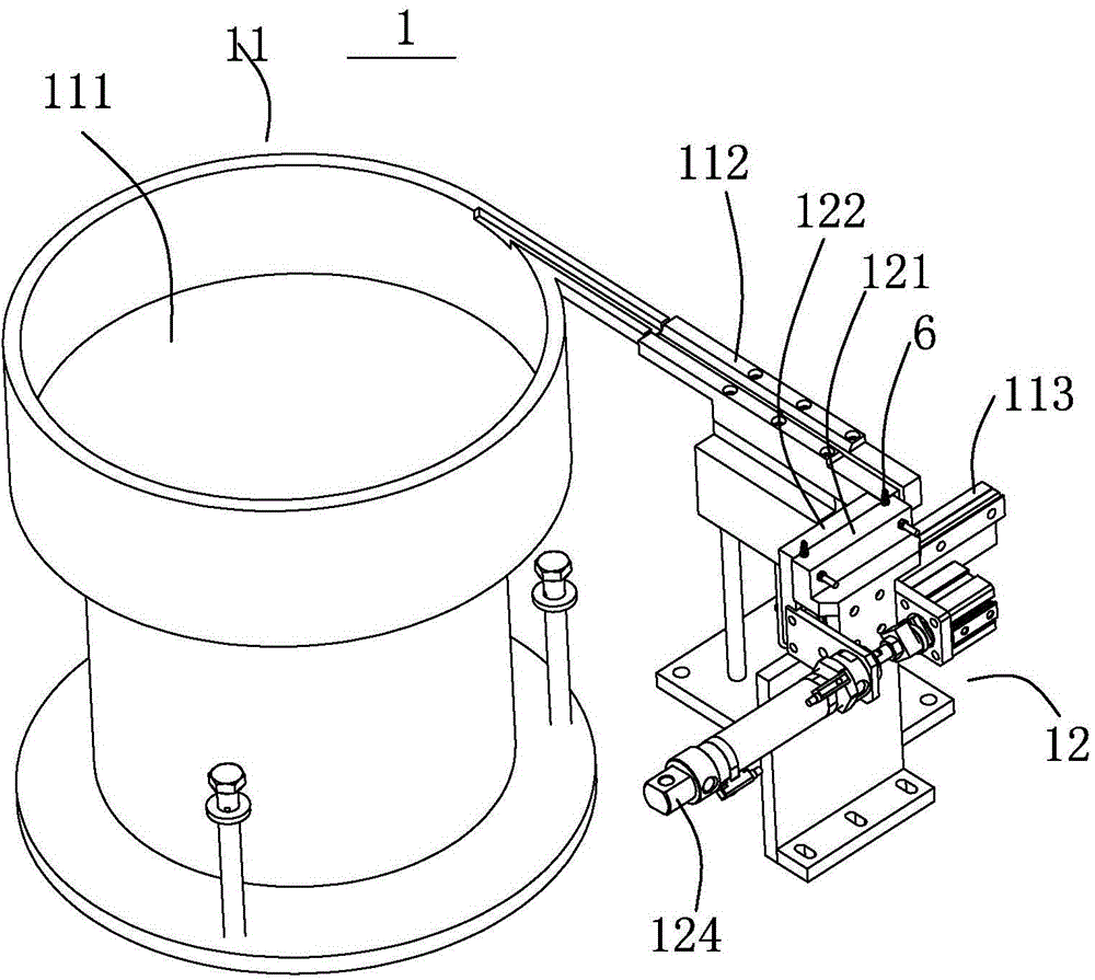
[0050] see Figure 1 to Figure 22 , the automatic pin grinding method provided by the present embodiment, which includes the following steps:

[0051] 1) A vibratory material selection mechanism 1 is set, and the vibratory material selection mechanism 1 includes a vibratory discharge assembly 11 and a moving material receiving assembly 12; Position assembly 22; a positioning detection mechanism 3 is provided, and the positioning detection mechanism 3 includes a divider turntable assembly 31, a pin detection assembly 32, and a defective rejection assembly 33; a material retrieving mechanism 4 is provided, and the retrieving mechanism 4 includes a material retrieving assembly 41. Feed and transposition assembly 42; a pin grinding mechanism 5 is provided, and the pin grinding mechanism 5 includes a belt roller assembly 51 and a grinding knife assembly 52; Each mechanism acts in coordination; wherein, the material grabbing mechanism 2 is arranged between the vibrating material se...


PUM


Abstract

The invention discloses an automatic insertion pin automatic grinding machine, which comprises a vibration material selection mechanism, a material grasping mechanism, a positioning detection mechanism, a material taking mechanism, an insertion pin grinding mechanism and an electric control mechanism, wherein the vibration material selection mechanism comprises a vibration material discharging assembly and a moving material collecting assembly, the material grasping mechanism comprises a material grasping assembly and a material grasping position changing assembly, the positioning detection mechanism comprises a divider turntable assembly, an insertion pin detection assembly and a defective product removing assembly, the material taking mechanism comprises a material taking assembly and a material taking replacing assembly, the insertion pin grinding mechanism comprises a belt rolling wheel assembly and a grinding cutter assembly, the electric control mechanism is electrically connected with each mechanism, and controls each mechanism to act in a coordinated way, the material grasping mechanism is arranged between the vibration material selection mechanism and the positioning detection mechanism, and the material taking mechanism is arranged between the positioning detection mechanism and the insertion pin grinding mechanism. The invention also discloses an automatic grinding method adopted by the grinding machine. The automatic grinding machine and the automatic grinding method have the advantage that the high-efficiency and high-quality automatic grinding of earphone insertion pins is realized.

Description

technical field [0001] The invention relates to the technical field of electronic product processing, in particular to an automatic pin grinding method and a grinding machine. Background technique [0002] The pins of electronic products such as earphone pins in the prior art are more commonly used, and the output is larger, and the models are also more. The usual earphone pin is a 3.5mm four-level pin, including four metal parts coaxially sleeved in sequence and an insulating layer for isolating the four metal parts from each other. Four welding pads are formed on the rear end for connecting with the earphone core wire. The four welding pads are arranged to form a welding part. The length of the welding part is 3.4-4.6mm, and the total length of the earphone pin is 17.4- 18.8mm. Generally, welding parts, punching parts, etc. are designed. After the initial processing, the surface of the product has uneven defects and needs to be further polished. [0003] The traditional...

Claims


Application Information

Patent Timeline
IPC IPC(8): B24B19/00B24B1/00B65G47/90B65G27/04B07C5/00B07C5/02B07C5/36
CPCB07C5/02B07C5/36B24B19/00B24B41/005B65G47/90B65G2201/02
Inventor 黄晖傅华良
Owner 浦北瀛通智能电子有限公司
Why Eureka
Try Eureka