
Crane steel wire rope anti-swing system

A technology for hoisting steel wire ropes and steel wire ropes, which is applied in the direction of load hanging components, transportation and packaging, etc. It can solve the problems of unbalanced force on the steel wire ropes, large torque of the reducer, inconvenient daily maintenance, etc., and achieves simple structure, reduced torque, Ease of repair and maintenance

Inactive Publication Date: 2015-04-01
DALIAN HUARUI HEAVY IND CRANE CO LTD +1
View PDF9 Cites 11 Cited by
  • Summary
  • Abstract
  • Description
  • Claims
  • Application Information

AI Technical Summary

Problems solved by technology

[0003] In order to solve the problems existing in the eight-rope anti-sway system in the prior art, such as large force on the steel wire rope, large torque of the reducer, unbalanced force on the steel wire rope, short life and inconvenient daily maintenance, the present invention proposes the following technical solutions: a crane Wire rope anti-sway system, including motor, reducer, brake, reel installed on the trolley frame and connected in sequence

Method used


Image

  • Crane steel wire rope anti-swing system
  • Crane steel wire rope anti-swing system
  • Crane steel wire rope anti-swing system

Examples


Embodiment Construction

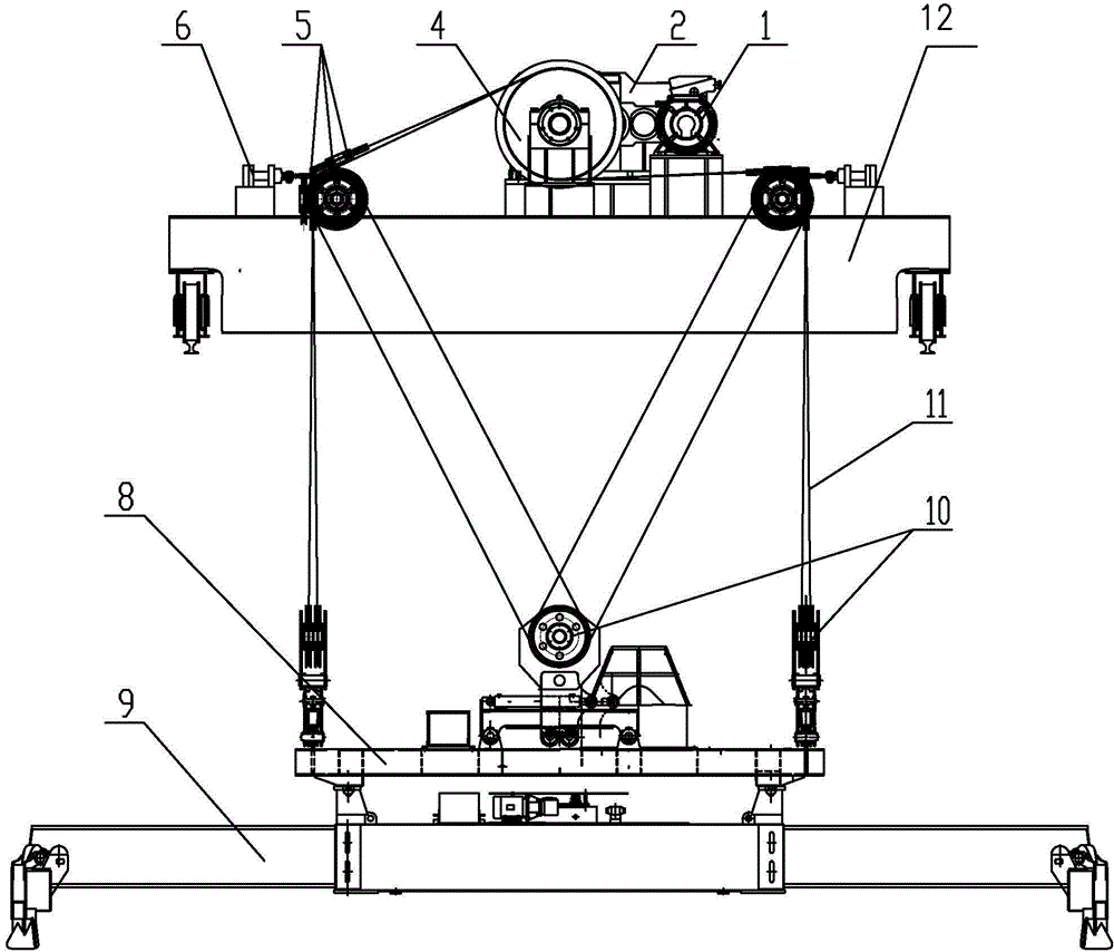
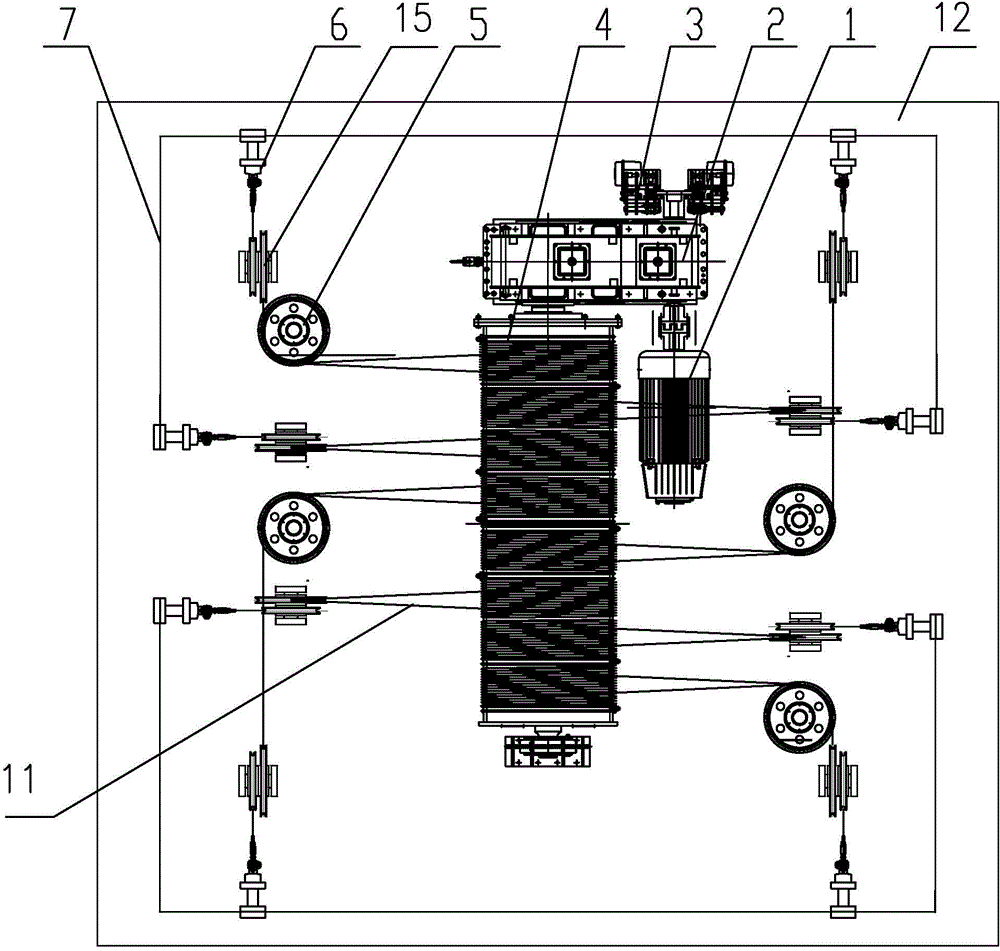
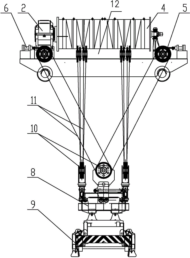
[0011] The crane wire rope anti-sway system of the present invention includes a motor 1, a reducer 2, a brake 3 and a reel 4 which are installed on the trolley frame 12 and connected in sequence. The bottom of the hoisting wire rope 11 is wound around the lower pulley group 10 on the upper frame 8 of the spreader. The spreader 9 is suspended below the upper frame 8 of the spreader. Its characteristics are: 8 hoisting wire ropes 11 wound on the drum 4 pass through the upper pulley block 5, and then guided by the steering wheel 15, the wire rope collar 14 at the end of the rope is fixed on the trolley evenly and symmetrically through the pin shaft 13 The piston rods of 8 hydraulic cylinders 6 on the four sides of frame 12 are connected, and 8 hydraulic cylinders 6 are divided into two groups, and every 4 hydraulic cylinders 6 cylinder bodies are connected in series with hydraulic cylinder connection pipelines 7. The upper pulley block 5 and the steering wheel 15 form the upper ...


PUM


Abstract

The invention discloses a crane steel wire rope anti-swing system. The crane steel wire rope anti-swing system comprises a motor, a reducer, a brake and a winding drum, which are mounted on a trolley frame and sequentially connected, wherein the lower parts of hoist ropes are twisted on a lower pulley block on an upper sling rack; the crane steel wire rope anti-swing system is characterized in that the eight hoist ropes twisted on the winding drum pass through an upper pulley block and a steering wheel, and steel wire rope lantern rings at the ends of the hoist ropes are respectively connected with piston rods of eight hydraulic cylinders which are symmetrically and uniformly fixed on the four sides of the trolley frame; the eight hydraulic cylinders are divided into two groups; every four hydraulic cylinder blocks are connected in series through hydraulic cylinder connecting pipelines. With the adoption of the technical scheme, the crane steel wire rope anti-swing system disclosed by the invention is simple in structure, the anti-swing effects of the steel wire ropes are obvious, the service life of the steel wire rope is effectively prolonged, and conveniences are brought to routine maintenance and repair of the equipment; the steel wire ropes are twisted in a multi-magnification manner, and the magnification factor is two, so that the pull of the steel wire ropes is only half of that in the prior art, and the torque of the winding drum can be reduced. Therefore, the specification of the reducer can be reduced, and the manufacturing cost can be lowered.

Description

technical field [0001] The invention is applicable to various container cranes and other lifting equipment with similar container spreaders. Background technique [0002] When handling containers, in order to facilitate the driver's operation and improve work efficiency, users have anti-sway requirements for the spreaders of container gantry cranes. Different wire rope winding systems have different anti-sway effects. ZL03117018.8 proposes a two-way anti-sway system for cranes. The patented 8-rope winding method, when applied to a large container crane, the force on the wire rope is large, the torque of the reducer is large, and the force on the 8 wire ropes is unbalanced, resulting in a short life of the wire rope. . The end of the wire rope is fixed on the hanger, which is not convenient for daily maintenance. At the same time, there is no specific implementation method when the multi-rate winding method of the wire rope is missing. Contents of the invention [0003] I...

Claims


Application Information

Patent Timeline
Patent Type & Authority Applications(China)
IPC IPC(8): B66C13/06
CPCB66C13/06
Inventor 庄云海吴刚李文杰周来
Owner DALIAN HUARUI HEAVY IND CRANE CO LTD
Learn More