Vertical continuous tempering furnace

A tempering furnace and vertical technology, which is applied in the field of vertical continuous tempering furnace, can solve the problems of high workpiece temperature and low production capacity of tempering furnace.

Active Publication Date: 2015-04-01
WENTON IND EQUIP JIANGSU
View PDF6 Cites 5 Cited by
  • Summary
  • Abstract
  • Description
  • Claims
  • Application Information

AI Technical Summary

Problems solved by technology

[0002] After the lamp is assembled, in order to eliminate the internal stress generated during the assembly, a continuous tempering furnace is generally used for stress relief treatment. The entrance and exit closed door is designed, and the heating adopts air supply from both sides of...

Method used


Image

  • Vertical continuous tempering furnace
  • Vertical continuous tempering furnace
  • Vertical continuous tempering furnace

Examples


specific Embodiment approach

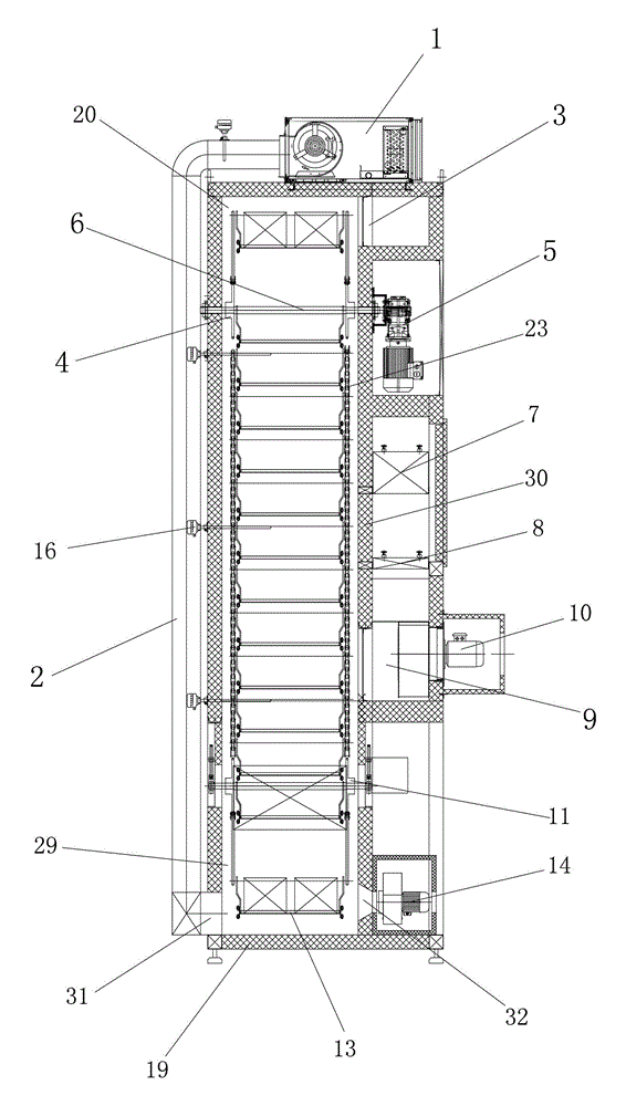
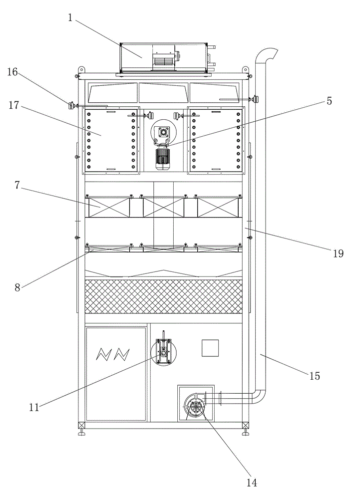
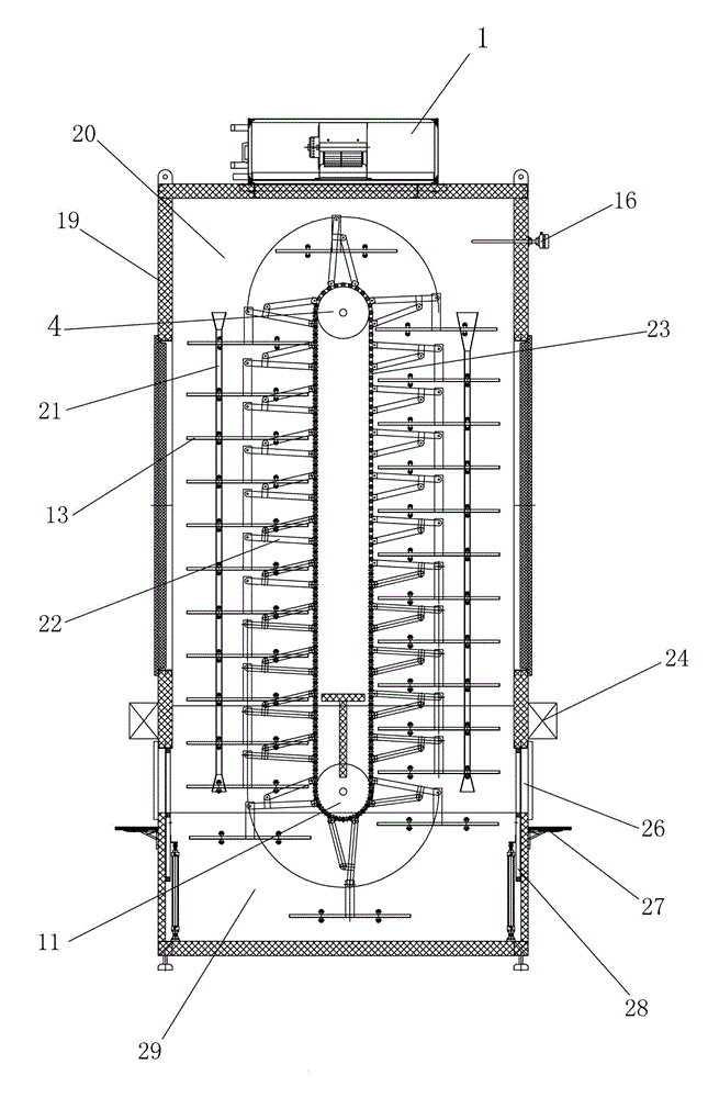
[0021] Such as figure 1 , figure 2 , image 3 Shown, a kind of vertical continuous tempering furnace comprises furnace body 19, and furnace body 19 adopts frame welding structure, inner plug insulation cotton, is provided with heating zone 20 and cooling zone 29 in the furnace body 19; Heating zone 20 and cooling zone Feeding and discharging opening 26 are arranged between the districts 29; Feeding and discharging opening 26 are located in the cooling zone 29; The inner side wall of the heating zone 20 is provided with an air supply passage through the partition plate 30, and the air supply passage is provided with an air inlet passage opening 9 and The air outlet channel port 3; the air outlet channel port 3 is located at the inner top of the furnace body 19; the air inlet channel port 9 is used for air suction, and the air outlet channel port 3 is used for air supply. The temperature of the channel is more uniform than that of the air supply on both sides; the furnace bod...


PUM


Abstract

The invention discloses a vertical continuous tempering furnace which comprises a furnace body, wherein a heating zone and a cooling zone are arranged in the furnace body; charging and discharging ports are formed between the heating zone and the cooling zone; an air supply channel is formed in the inner side wall of the heating zone; heating pipes, a circulating fan and filters are arranged on the furnace body; a drive sprocket and a tensioner sprocket are arranged in the furnace body; the drive sprocket is connected with a drive motor; a circulating chain is connected between the drive sprocket and the tensioner sprocket; hanging baskets are connected onto the circulating chain; an air conditioning refrigeration unit is arranged at the top of the furnace body and communicated with a cooling air inlet; and a cooling exhaust fan is arranged on the cooling zone. The vertical continuous tempering furnace is energy-saving; the temperature uniformity and stability are good with adoption of an upper feeding and lower returning type air supply structure on the furnace body, a one-way cycle operation manner is adopted, and the equipment occupation area is reduced due to height increase; and meanwhile, an air conditioning is adopted to cool a workpiece, the workpiece temperature is reduced to be lower than 40 DEG C during workpiece discharging, and the workpiece temperature during workpiece taking is reduced.

Description

technical field [0001] The invention relates to the field of tempering equipment, in particular to a vertical continuous tempering furnace. Background technique [0002] After the assembly of the lamp, in order to eliminate the internal stress generated during assembly, the continuous tempering furnace is generally used for stress relief treatment at present. The entrance and exit closed door is designed, and the heating adopts air supply from both sides of the bottom and return air from the top. This type of tempering furnace has a low capacity, and after the workpiece is taken out after tempering, the temperature of the workpiece is high, so it cannot directly enter the next process, and must wait. It can enter the next process after cooling. Contents of the invention [0003] The object of the present invention is to overcome the disadvantages of the above-mentioned prior art and provide a vertical continuous tempering furnace with simple structure, convenient operatio...

Claims


Application Information

Patent Timeline
IPC IPC(8): C21D9/00
CPCC21D9/00
Inventor 夏建明
Owner WENTON IND EQUIP JIANGSU
Why Eureka
Try Eureka