Modular energy dissipating device and anti-collision pipeline thereof

An energy-dissipating device and a modular technology, applied in water conservancy projects, climate change adaptation, shipping equipment, etc., can solve problems such as poor anti-collision ability, high production cost, unreasonable design, etc., achieve exquisite structural design, reduce production The effect of low cost and strong anti-corrosion ability

Active Publication Date: 2015-04-01
JIANGSU HONGYUAN TECHNOLOGY ENGINEERING CO LTD
View PDF8 Cites 3 Cited by
  • Summary
  • Abstract
  • Description
  • Claims
  • Application Information

AI Technical Summary

Problems solved by technology

[0004] The technical problem to be solved by the present invention is: in order to overcome the disadvantages of unreasonable design, complex structure, high production cost and poor anti-collision ability in the prior art, the present invention provides a modular energy dissipation device and its anti-collision pipeline

Method used


Image

  • Modular energy dissipating device and anti-collision pipeline thereof
  • Modular energy dissipating device and anti-collision pipeline thereof
  • Modular energy dissipating device and anti-collision pipeline thereof

Examples


Embodiment 1

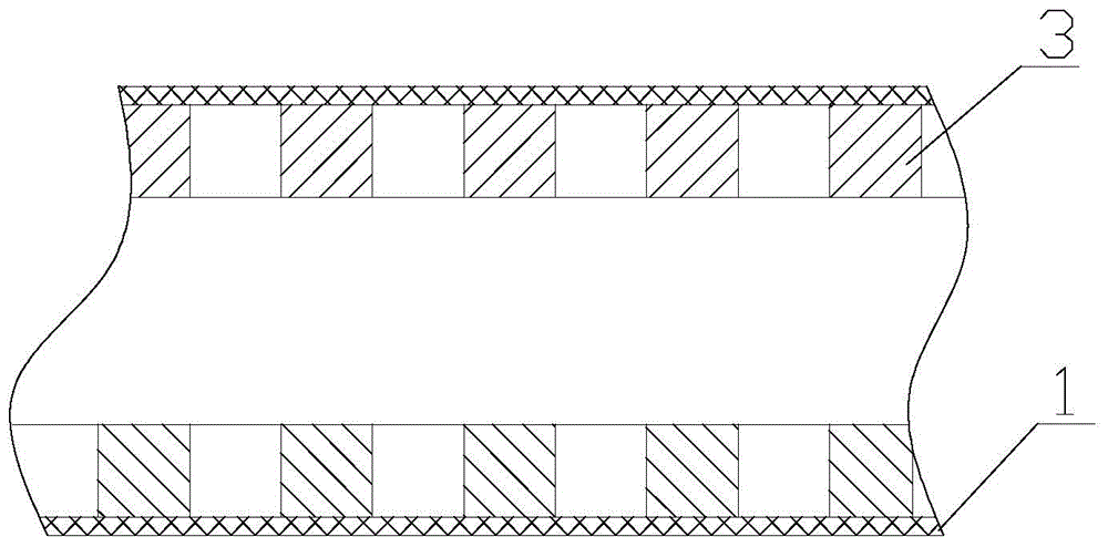
[0029] like figure 1 As shown, a kind of anti-collision pipeline 100 of the present invention comprises an outer tube 1 and several rubber rings 3, each rubber ring 3 is arranged coaxially with the outer tube 1, and the outer surface of each rubber ring 3 is matched with the inner wall of the outer tube 1 . The outer surface of each rubber ring 3 is close to the inner wall of the outer tube 1 , and the outer surface of the rubber ring 3 is closely matched with the inner wall of the outer tube 1 . There is a distance between two adjacent rubber rings 3; on the inner wall of the outer tube 1, a fixing device is provided to prevent each rubber ring 3 from sliding horizontally. The rubber ring 3 is a rubber tire.

[0030] The outer pipe 1 is a composite material pipe. The composite material is made of glass fiber reinforced plastic. The glass fiber reinforced plastic matrix material is one of unsaturated resin, isophthalic resin, ophthalmic resin, vinyl resin, epoxy resin, bis...

Embodiment 2

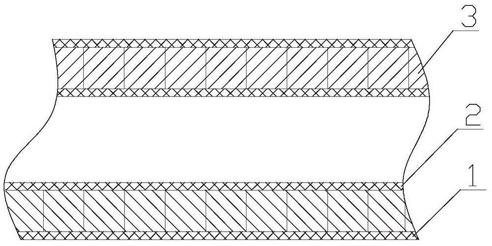
[0032] like figure 2 As shown, this embodiment is roughly the same as Embodiment 1, the difference is that an inner tube 2 is also provided in the rubber ring 3, and each rubber ring 3 is sleeved on the inner tube 2, and the inner tube 2, the rubber ring 3 and The outer tube 1 is arranged coaxially, and the inner tube 2 and the outer tube 1 are composite material tubes; two adjacent rubber rings 3 are tightly connected. After the anti-collision pipeline 100 has a certain length, the two ends of the anti-collision pipeline 100 are provided with sealing covers. The outer pipe 1 can also be a steel pipe. When the outer pipe 1 is a steel pipe, the outer surface and / or inner surface of the outer pipe 1 has an anti-corrosion layer, the anti-corrosion layer is a composite material layer or a paint layer, and generally the inner surface of the outer pipe 1 can be coated with a paint layer, The outer surface of the outer tube 1 is coated with a composite material layer.

Embodiment 3

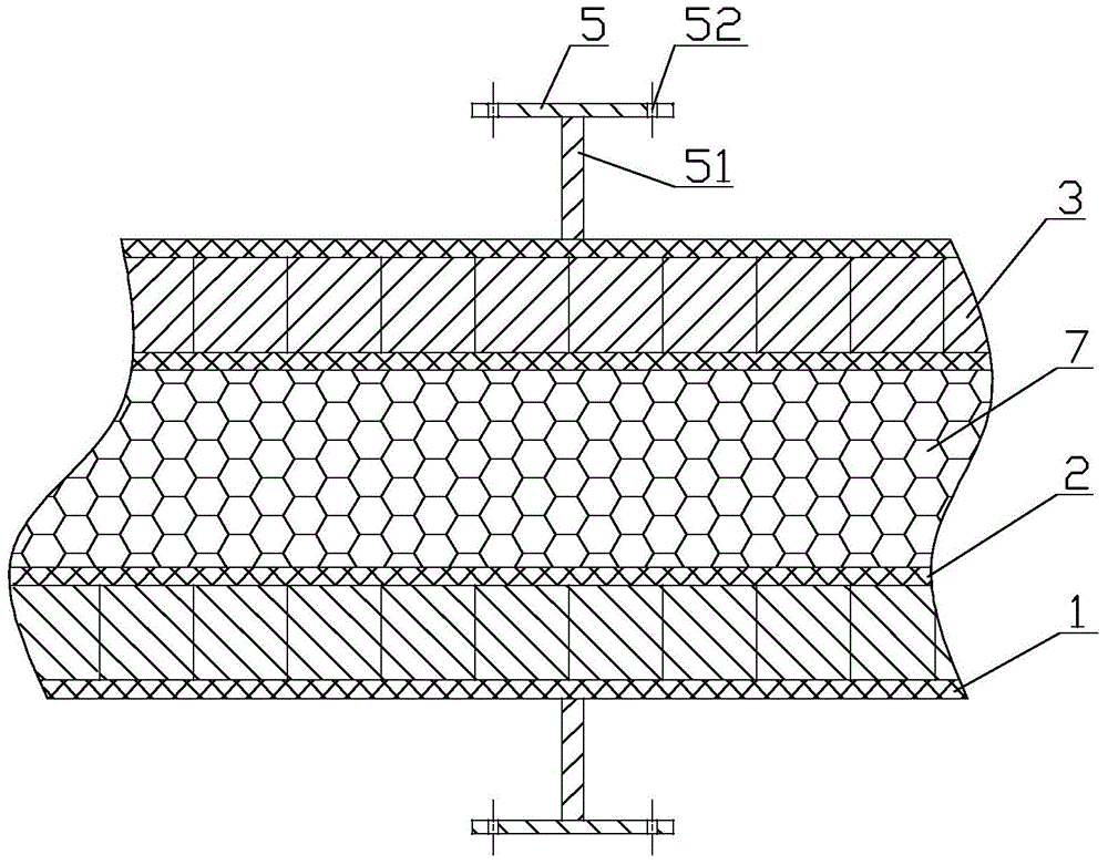
[0034] like image 3 As shown, this embodiment is substantially the same as Embodiment 2, the difference is that there is a filler 7 inside the inner pipe 2, and the filler 7 is polyurethane foam, polyvinyl chloride foam, carbon foam, PEI foam and PMI foam, Balsa wood , paulownia wood, fir or strong core felt. The filler 7 can fill up the lumen of the inner tube 2 .

[0035] like image 3 , Figure 4 As shown, an installation method of the anti-collision pipeline 100 of the present invention, that is, a schematic structural diagram of a modular energy dissipation device, the modular energy dissipation device includes an anti-collision pipeline 100 and a connection fixing seat, and the anti-collision pipeline 100 is fixed On the connection and fixing seat, the anti-collision pipe 100 adopts the anti-collision pipe of the present invention. Wherein, the two anti-collision pipelines 100 can be connected through the connecting loop flange 6 in the length direction, and the ant...


PUM


Abstract

The invention relates to a modular energy dissipating device and an anti-collision pipeline of the modular energy dissipating device. The modular energy dissipating device comprises the anti-collision pipeline and a connection fixing base. The anti-collision pipeline comprises an outer pipe, a plurality of rubber rings and an inner pipe. The inner pipe, the rubber rings and the outer pipe are arranged coaxially. The outer surfaces of the rubber rings are matched with the inner walls of the outer pipe. After the anti-collision pipeline has a certain length, sealing cover boards are arranged at the two ends of the anti-collision pipeline. The anti-collision pipeline adopts the rubber rings as buffer units, the pipes are arranged inside and outside the rubber rings, structural design is delicate, and the manufacturing cost is reduced on the premise of guaranteeing the anti-collision capacity; besides, the anti-corrosion capacity is high, and good anti-corrosion performance is ensured. The width and height of an anti-corrosion facility can be increased after the anti-corrosion pipeline is fixed to the connection fixing base, and the requirement for anti-corrosion performance of bridges is met.

Description

technical field [0001] The invention relates to a modular energy dissipation device and an anti-collision pipeline thereof. Background technique [0002] The anti-collision device is mainly used for the protection of the pier, so that the impact damage of the hull to the pier is minimized, and it also plays a certain role in protecting the hull. [0003] The anti-collision devices in the prior art all use steel boxes to cover the outside of the pier for protection. This steel box has a large weight, and its service life is relatively short due to long-term immersion in water, especially in highly corrosive seawater. After being hit, they are all in a scrapped state and can only be used once. There are also some anti-collision devices that adopt a combined structure. Not guaranteed. Contents of the invention [0004] The technical problem to be solved by the present invention is: in order to overcome the disadvantages of unreasonable design, complex structure, high produc...

Claims


Application Information

Patent Timeline
Patent Type & Authority Applications(China)
IPC IPC(8): E02B3/26
CPCE02B3/26E02B2201/04Y02A30/30
Inventor 蒋超
Owner JIANGSU HONGYUAN TECHNOLOGY ENGINEERING CO LTD
Why Eureka
Try Eureka