Home decoration toilet pipe-side floor drain treatment process

A treatment process and toilet technology, applied to water supply devices, waterway systems, drainage structures, etc., can solve the problems of filling mortar and pipe edge falling off, frequent pipe edge vibration, poor adhesion, etc., to achieve long service life and excellent flexibility , excellent effect

Inactive Publication Date: 2015-04-01
厦门顶巢建筑科技有限公司
View PDF6 Cites 8 Cited by
  • Summary
  • Abstract
  • Description
  • Claims
  • Application Information

AI Technical Summary

Problems solved by technology

Due to the poor adhesion of ordinary mortar, it cannot be well bonded to the excavated surface and plastic pipes, and the pipe edge vibrates frequently, while ordinary mortar is a rigid material, so it is easy to cause the filling mortar to fall off from the pipe edge, forming a leaky channel

Method used


Image

  • Home decoration toilet pipe-side floor drain treatment process
  • Home decoration toilet pipe-side floor drain treatment process
  • Home decoration toilet pipe-side floor drain treatment process

Examples


Embodiment 1

[0025] A process for treating floor drains on the pipe side of a home improvement bathroom includes the following steps:

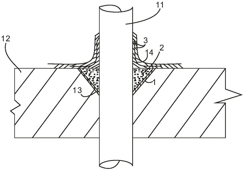
[0026] S1, reference figure 1 As shown, on the concrete floor 12 around the root of the plastic pipe 11, an inverted conical groove 13 is cut out with a chisel. The depth and width depend on the specific situation. In principle, the wider the deeper the better. But the depth generally does not exceed one-third of the thickness of the floor. Remove the scum in the tank and wash with water.

[0027] S2. Paint the groove with an interface waterproofing agent for 1-2 times under humid conditions; the interface waterproofing agent is composed of liquid and powder, and the powder is composed of the following components and mass parts: waterproof glue 370-450 Parts; 1-2 parts of defoamer; 1-2 parts of preservative; 1-2 parts of wetting agent; 550-630 parts of water; the powder consists of the following components and parts by mass: 800-1000 parts of cement; 400 parts...

Embodiment 2

[0037] Referring to Example 1, the difference from Example 1 is:

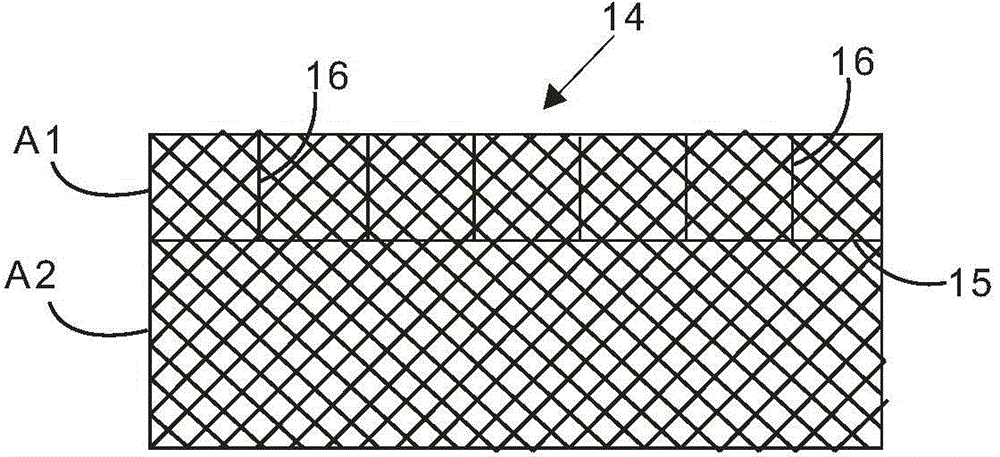
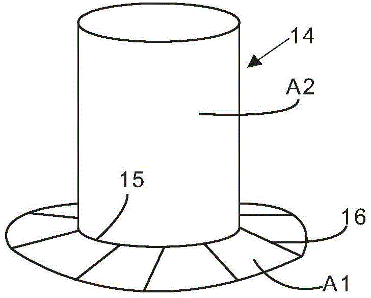
[0038] First, in S4 of Example 1, see figure 1 As shown, a polyester cloth 14 is sandwiched between the two pipe-fixed waterproof glues that are painted. That is, after applying the first pipe-fixing waterproof glue 3, put on the polyester cloth 14, and then apply the second pipe-fixing waterproof glue 3 on the polyester cloth. Among them, polyester cloth such as figure 2 As shown, it is generally a rectangular piece of cloth. The processing method is as follows: first form a crease 15 and divide it into A1 and A2 sides; then form multiple torn edges 16 perpendicular to the crease 15 at equal intervals on the A1 side; and finally Roll the A2 surface into a cylinder, and unfold the A1 surface around the crease 15 to form image 3 Shown.

[0039] Then, after S4, S5 is included, and the waterproof slurry is applied to the pipe-fixed waterproof glue. The waterproof slurry 1 is also composed of powder and liquid, whe...

Embodiment 3

[0044] Referring to Example 2, the difference from Example 2 is that in S3, the multifunctional emulsion and the quick-setting cement are mixed at a weight ratio of 0.5:1.


PUM


Abstract

The invention provides a home decoration toilet pipe-side floor drain treatment process. The treatment process comprises the steps of S1, digging out a groove in the concrete floor around the root of a pipeline, removing residue in the groove and cleaning the groove by use of water, S2, coating the groove with an interface waterproof agent once or twice under the condition of moist, S3, evenly mixing a multifunctional emulsion with quick-setting cement in the weight ratio of (0.3-0.5): 1 into a paste, applying the paste into the groove, and compacting and trowelling, S4, after the filler in the groove is solidified, coating the root and the four sides of the pipeline with a secondary pipe fixation waterproof glue. According to the home decoration toilet pipe-side floor drain treatment process, at least three waterproof layers, namely the interface waterproof agent layer, the mixed layer of the multifunctional emulsion and the quick-setting cement, and the waterproof layer of the pipe fixation waterproof glue are provided. Due to triple waterproofing operations, the waterproof effect is excellent and the service life is long.

Description

Technical field [0001] The invention relates to the technical field of building materials, in particular to a process for treating floor drains at the pipe side of a home improvement bathroom. Background technique [0002] In the waterproofing of home furnishings, the treatment of the pipe edges of plastic materials such as hydropower PVC and PP is a key point affecting the entire waterproof system. Such as: the side of the sewer pipe, the side of the wall pipe, the side of the main sewage pipe. The engineering construction is carried out by taking holes or excavating stainless steel, and then passing the plastic pipe through the base layer or inlaying it in the base layer, so that there is a large gap between the pipe side and the base layer. The construction party of this gap is mainly through ordinary cement mortar. Repair it. Due to the poor adhesion of ordinary mortar, it cannot bond well with the excavation surface and the plastic pipe, and the pipe edge vibrates frequent...

Claims


Application Information

Patent Timeline
Patent Type & Authority Applications(China)
IPC IPC(8): E03F5/04E04B1/64
CPCE03F5/0407E03F5/0409
Inventor 刘可罡林志炼
Owner 厦门顶巢建筑科技有限公司
Why Eureka
Try Eureka