Method for visually representing spatial distribution and content of water in cement-based material

A technology of cement-based materials and spatial distribution, applied in the direction of material analysis using radiation, can solve problems such as difficulties in cement-based materials, and achieve the effect of accurately predicting changes

Active Publication Date: 2015-04-01
CHINA UNIV OF MINING & TECH
View PDF6 Cites 20 Cited by
  • Summary
  • Abstract
  • Description
  • Claims
  • Application Information

AI Technical Summary

Problems solved by technology

[0004] Aiming at the difficulty of quantitatively analyzing moisture intrusion into cement-based materials, the present invention prov

Method used


Image

  • Method for visually representing spatial distribution and content of water in cement-based material
  • Method for visually representing spatial distribution and content of water in cement-based material
  • Method for visually representing spatial distribution and content of water in cement-based material

Examples


Embodiment 1C

[0033] Embodiment 1 CT imaging experiment

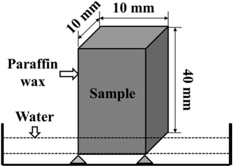
[0034] Step 1: Firstly, the cement slurry is prepared by using ordinary Portland cement. After the sample is formed for 24 hours, the formwork is removed and placed in a standard curing room with a humidity of 95% and a temperature of 20°C for 1 year, and then the specimen is cut into 10mm×10mm× prisms of 40 mm in diameter, and dried in an oven at 105° C. to constant weight to obtain the sample.

[0035] Step 2: Then use paraffin to seal all the end faces and sides of the sample except the water-immersed surface to prevent moisture from intruding into the inside of the sample from the side, then put the sample into a flat-bottomed plastic container, and support the water-immersed surface with a small block.

[0036] Step 3: Place the flat-bottomed plastic container containing the sample on the X-CT imaging device table, inject water into the flat-bottomed plastic container so that the liquid level is 2mm higher than the sample immers...

Embodiment 2

[0038] Embodiment 2 typical capillary water absorption CT image

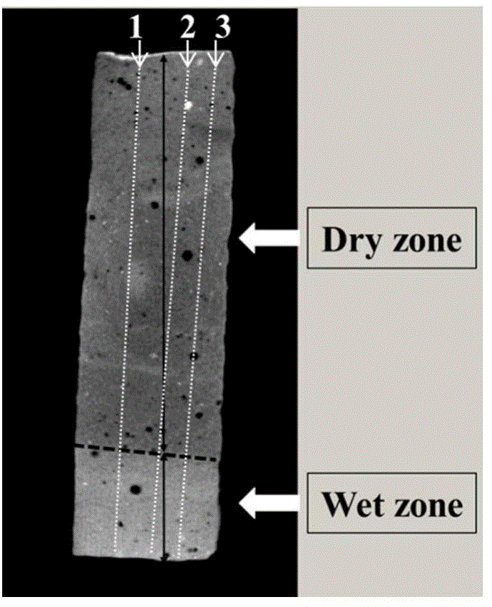
[0039] Taking the water-cement ratio of 0.35 cement paste as an example after absorbing water for 20 minutes, the typical CT imaging of capillary water absorption experiment is as follows: figure 2 As shown, the sample can be divided into two regions according to the location of water absorption: the wet region and the dry region, and the brightness of the bottom wet region is greater than that of the upper dry region. In addition, the height of the bright area on the left side of the cement paste is higher than that on the right side. This is because the cement-based composite material is a heterogeneous material, and the size and volume distribution of the capillary pores are not uniform, resulting in a slow rate of water intrusion into the material. difference.

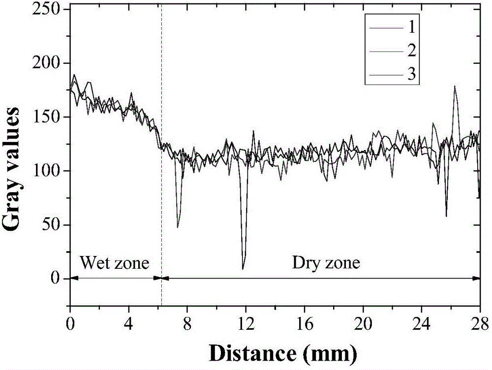
[0040] In order to accurately characterize the intrusion depth of water in the slurry, three straight lines were randomly selected on the 2D CT im...

Embodiment 3

[0041] The influence of embodiment 3 ground slag dosage

[0042] Figure 4 CT images for in situ observation of water intrusion into cement paste with 0% and 10% fine slag content at different times. With the increase of capillary water absorption time, under the action of capillary adsorption force, the water continuously climbs from the bottom to the top of the sample. Before 60 minutes, the water can quickly invade into the inside of the sample in a short time. When the water absorption time increases from 60 minutes to 270 minutes The capillary water absorption rate is lower than before. It can be seen that the capillary water absorption process of cement paste is rapid in the early stage and slow in the later stage. In addition, it can be observed from the image that the water front does not remain at a fixed position, and the water intrusion depth is deeper at the left and right ends of the slurry in the early stage, and the water front is located in the middle of the ...


PUM


Abstract

The invention discloses a method for visually representing spatial distribution and content of water in a cement-based material. The cement-based material which has good forming property and is maintained for a certain age is taken and dried to obtain a sample; all end surfaces and side surfaces, excluding a wetted surface, of the sample are sealed by paraffin; the sample is put in a flat-bottom container, and the wetted surface is supported by small cushion blocks; the flat-bottom container is put on an X-CT (X-Ray computed tomography) imaging device table, water is injected into the flat-bottom container until the water surface is higher than the wetted surface of the sample for a certain distance, a capillary water absorption experiment is performed, meanwhile, an X-CT imaging device is started, and the water soaked sample is subjected to X-CT imaging; an X-CT image is subjected to gray scale analysis, and change of capillary water absorption depth of the sample is obtained; the capillary water absorption depth coefficient is obtained by means of capillary water absorption depth and time; and change of capillary water absorption quality of the sample is obtained by means of the capillary water absorption depth coefficient and sample porosity. According to the method, change of the water soaked depth can be quantitatively represented, and the capillary water absorption quality change can be accurately predicted.

Description

technical field [0001] The invention relates to the field of durability research and application of cement-based materials, in particular to a visual representation of the spatial distribution and content of moisture in cement-based materials after capillary water absorption. Background technique [0002] Moisture not only provides a convenient transport carrier for erosion ions (sulfate ions, chloride ions, etc.) to enter or calcium ions to dissolve into cement-based composite materials, but also acts as the main medium to cause material shrinkage or freeze-thaw damage under alternating temperature and humidity conditions. destroy. Therefore, a full understanding of the moisture transport behavior is helpful for a reasonable analysis of the durability failure law. [0003] There are three main ways of moisture migration in concrete: penetration, capillary water absorption, and gas phase diffusion. Permeation mainly refers to the transport behavior of saturated water under...

Claims


Application Information

Patent Timeline
IPC IPC(8): G01N23/04
Inventor 刘志勇张云升吕恒林吴寒
Owner CHINA UNIV OF MINING & TECH
Why Eureka
Try Eureka