Type critical illumination system for extreme ultra-violet lithography

An extreme ultraviolet lithography and lighting system technology, which is applied in the field of quasi-critical lighting systems, can solve the problem of the lack of placement space for the secondary vacuum isolation system and the chip removal system, the compactness of the lighting system and the objective lens system layout, and the increase in the difficulty of component processing and adjustment. The difficulty of calibration and other issues can improve the efficiency of light energy collection, expand the space for light transmission, and reduce the difficulty of production.

Inactive Publication Date: 2015-04-01
CHANGCHUN INST OF OPTICS FINE MECHANICS & PHYSICS CHINESE ACAD OF SCI
View PDF9 Cites 6 Cited by
  • Summary
  • Abstract
  • Description
  • Claims
  • Application Information

AI Technical Summary

Problems solved by technology

[0011] In order to solve the problem that the existing classical critical lighting system is only suitable for pure-spectrum light sources, it lacks a secondary vacuum isolation system that allows the light path to pass through, an extreme ultraviolet light filter and transmission film, and an effective space for the dandruff removal system, so it cannot be directly used to construct an extreme lighting system. Ultraviolet lithography system, at the same time, the lighting system and objective lens system used by it are too compact and irregular in layout, which increases the difficulty of processing various components and the difficulty of later assembly and calibration
On the other hand, the existing conventional blocking devices cannot change the position, angle and effective blocking area in the light path, and do not have the technical problem of continuously adjusting the uniformity of illumination in the light path. The present invention provides an extreme ultraviolet Critical Illumination System for Lithography

Method used


Image

  • Type critical illumination system for extreme ultra-violet lithography
  • Type critical illumination system for extreme ultra-violet lithography
  • Type critical illumination system for extreme ultra-violet lithography

Examples


Embodiment Construction

[0028] The present invention will be further described in detail below in conjunction with the drawings.

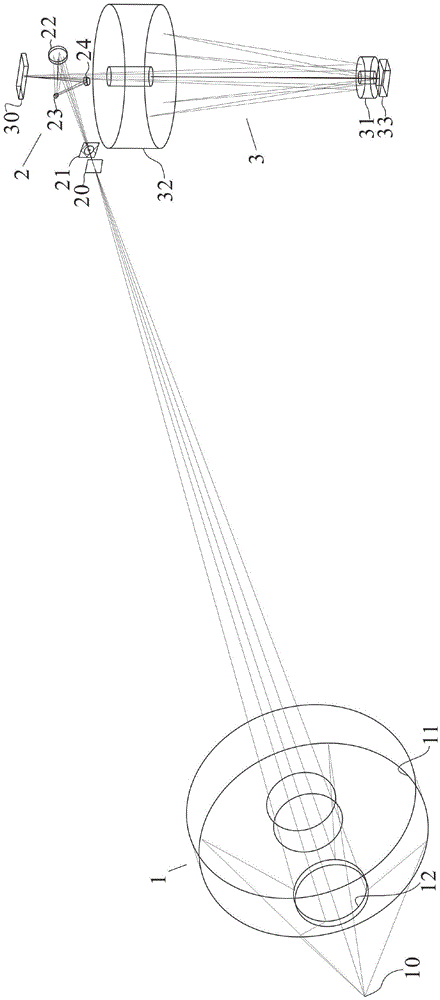
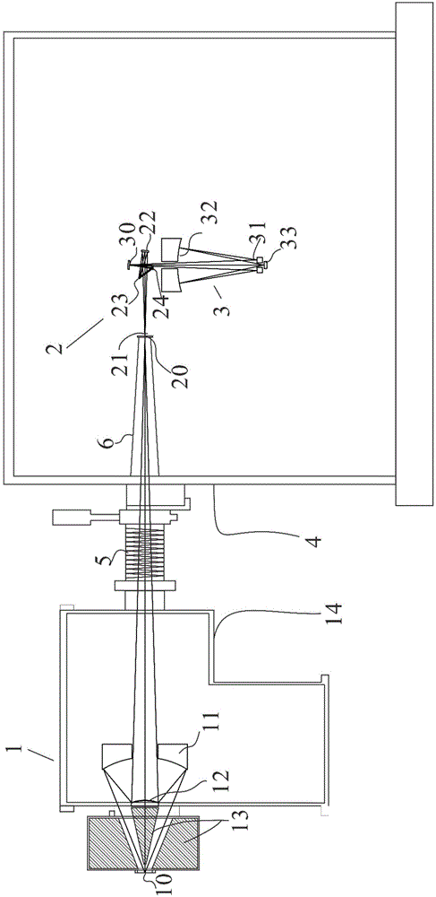
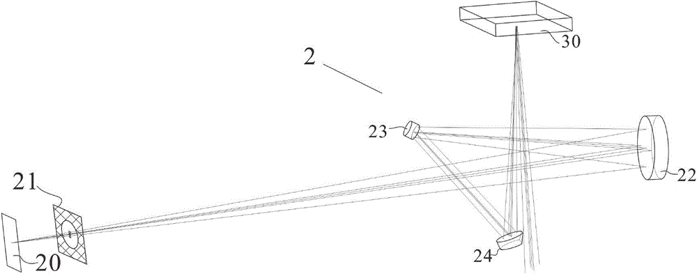
[0029] Such as Figure 1 to Figure 5 As shown, a critical-like lighting system for extreme ultraviolet lithography, the lighting system includes a light-concentrating system 1, a relay system 2, a lithography system, a vacuum box 4, a bellows 5, and a cone 6. The system 1 includes a light source 10, a condensing primary mirror 11, a condensing system secondary mirror 12, a swarf removing system 13, and a condensing system vacuum box 14. The swarf removing system 13 is arranged along the optical path on the rotational symmetry axis of the light cone of the light source 10 ; The condensing system secondary mirror 12 and the condensing primary mirror 11 are sequentially located behind the anti-dandruff system 13, the light source 10 is a wide-spectrum DPP light source, and the condensing system secondary mirror 12 and the condensing primary mirror 11 together form Schwartz· In...


PUM


Abstract

The invention relates to a type critical illumination system for extreme ultra-violet lithography, belonging to the field of a critical illumination system in an extreme ultra-violet lithography system. The type critical illumination system comprises a light condensing system, a relay system, a photoetching system vacuum tank body and a corrugated pipe, wherein the light condensing system comprises a light source, a light condensing primary mirror, a light condensing system secondary mirror, a scrap removing system and a light condensing system vacuum tank body; the scrap removing system is arranged on a symmetry axis of a light source emergent sector along a light path; the light condensing system secondary mirror and the light condensing primary mirror are sequentially arranged behind the scrap removing system, and the light source, the light condensing system secondary mirror and the light condensing primary mirror commonly form a Schwartz-Kierard system; the light condensing system secondary mirror and the light condensing primary mirror are both arranged in the light condensing system vacuum tank body; the front end of the scrap removing system is close to the light source, and the rear end of the scrap removing system is fixedly connected with the rear end of the light condensing system secondary mirror. According to the type critical illumination system, the light source collecting solid angle can reach 0.48Sr, the shielded center area is less than 25%, the luminous energy collecting efficiency is greatly improved, an effective action distance of the scrap removing system can be increased and the scrap removing effect can be well achieved.

Description

Technical field [0001] The invention belongs to the field of critical illumination systems in extreme ultraviolet lithography systems, and in particular relates to a critical-like illumination system for extreme ultraviolet lithography. Background technique [0002] The optical main structure of the lithography system usually includes two parts: the illumination system and the objective lens system, such as figure 2 As shown, the existing objective lens system 3 includes a mask surface 30, a primary lens 31 of the objective lens system 3 (that is, the entrance pupil of the objective lens system 3), a secondary mirror 32 of the objective lens system 3, and a wafer surface 33. After the illumination light is sequentially reflected by the mask surface 30, the objective lens system 3 primary mirror 31, and the objective lens system third mirror 32, the pattern on the mask surface 30 is finally projected on the wafer surface 33 and etched . [0003] The lighting system can be divided i...

Claims


Application Information

Patent Timeline
IPC IPC(8): G03F7/20
Inventor 王君王丽萍金春水谢耀周烽
Owner CHANGCHUN INST OF OPTICS FINE MECHANICS & PHYSICS CHINESE ACAD OF SCI
Why Eureka
Try Eureka