
Electromechanical integrated optimization method for sectional dimensions of ribs of metal truss type antenna housing

A metal truss-type, cross-sectional size technology, applied in electrical digital data processing, special data processing applications, instruments, etc., can solve the problem of not considering electromechanical integration design, etc., and achieve the effect of improving structural performance and cost

Inactive Publication Date: 2015-04-01
XIDIAN UNIV +1
View PDF3 Cites 21 Cited by
  • Summary
  • Abstract
  • Description
  • Claims
  • Application Information

AI Technical Summary

Problems solved by technology

The disadvantage of this method is that it only analyzes the influence of the metal truss radome on the electrical performance of the antenna, without considering the electromechanical integration design
[0005] In Wang Congsi's 2008 paper "Mechatronics Design and Analysis System for Large-scale Reflector Antenna Structure", he studied the antenna electromechanical integration technology and the theory of antenna combination structure, and used the accurate PO method to analyze the radiation electric field in the far area of ​​the antenna, and established the surface The hierarchical structure of the antenna parametric design solves the problem of automatic grid division of the combined structure composed of the back frame, reflector and central body, and realizes the electromechanical integrated design of the surface antenna structure. However, the electromechanical integrated design has not been applied to the metal truss in the radome

Method used


Image

  • Electromechanical integrated optimization method for sectional dimensions of ribs of metal truss type antenna housing
  • Electromechanical integrated optimization method for sectional dimensions of ribs of metal truss type antenna housing
  • Electromechanical integrated optimization method for sectional dimensions of ribs of metal truss type antenna housing

Examples


Embodiment Construction

[0026] The present invention will be described in further detail below with reference to the accompanying drawings.

[0027] refer to Figure 4 , the metal truss type radome, including ribs, central nodes, and skins. The ribs are connected together through the central nodes to form a triangle, and the skin covers the ribs and the central nodes.

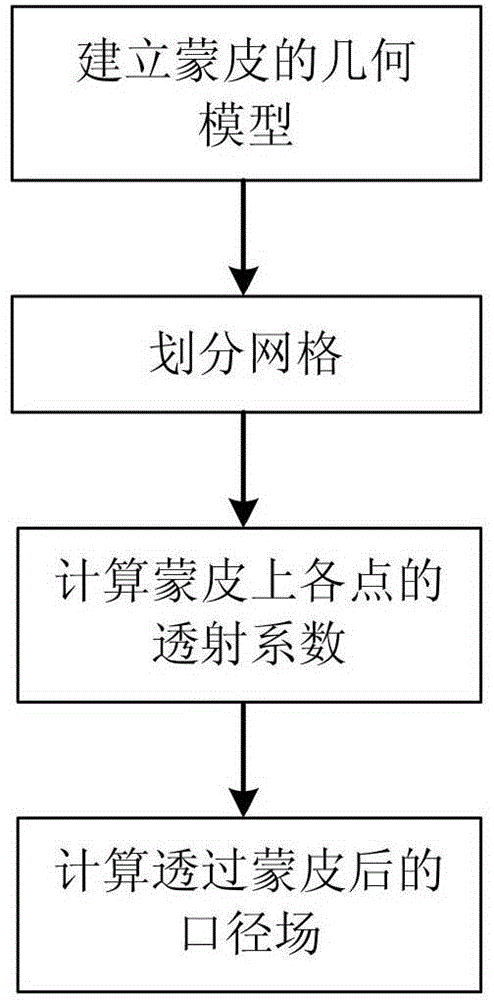
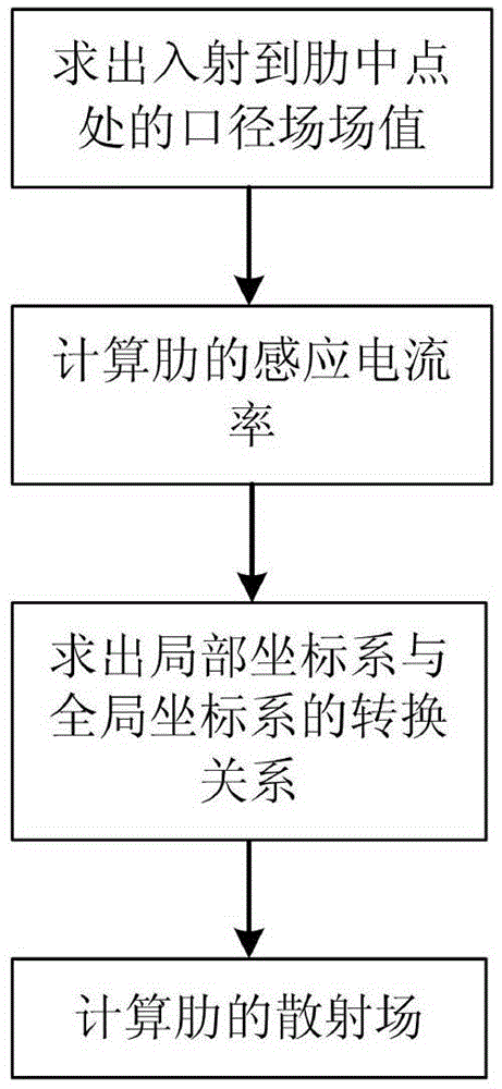
[0028] refer to figure 1 , the concrete steps of the present invention are as follows:

[0029] Step 1, according to the structural parameters and material parameters of the skin of the metal truss radome, calculate the transmission coefficient at each point on the skin by using the transmission line theory And according to the known antenna aperture field E(x,y), calculate the aperture field after passing through the radome: E ′ ( x , y ) = E ( x , ...


PUM


Abstract

The invention discloses an electromechanical integrated optimization method for sectional dimensions of ribs of a metal truss type antenna housing. The technical scheme of the invention is as follows: the method comprises the steps: calculating a far field generated by a skin-penetraed aperture field; calculating a scattered field of the ribs; adding the scattered field of the ribs to the far field generated by the skin-penetrated aperture field, so as to obtain a far field of an antenna enclosed by the housing; calculating the maximum displacement of an antenna housing node under the action of a load; calculating the weight of an antenna housing body; classifying the ribs according to heights of midpoints of the ribs, and establishing an optimization model by taking dimensions of middle ribs of a truss as design variables and taking the electrical properties, maximum node displacement and weight of an antenna system enclosed by the housing as optimization targets; solving the optimization model by using a particle swarm optimization algorithm, thereby obtaining an optimal comprehensive design scheme for various indexes. The method can be used for guiding the design of the sectional dimensions of the ribs of the metal truss type antenna housing and carrying out analysis and evaluation on the electromechanical comprehensive performance of the metal truss type antenna housing.

Description

technical field [0001] The invention belongs to the technical field of radar antennas, in particular to an electromechanical integration optimization method for the rib cross-sectional size of a metal truss type radome, which is used to guide the structural design of the metal truss type radome to optimize its structural performance and electrical performance. technical background [0002] A radome is a wave-transparent shell that protects the antenna from the natural environment. It is a covering made of natural or artificial dielectric materials, or a specially shaped electromagnetic window composed of a dielectric shell supported by a truss. A well-designed radome, in addition to the functions of protection, conductivity, reliability, concealment and decoration, can also prolong the service life of each part of the entire system, reduce life costs and operating costs, simplify design, and reduce maintenance costs , Ensure the accuracy of the antenna surface and position, ...

Claims


Application Information

Patent Timeline
Patent Type & Authority Applications(China)
IPC IPC(8): G06F17/50
Inventor 许万业李鹏段宝岩张志孝李志君仇原鹰王环崔传贞
Owner XIDIAN UNIV
Learn More