Airbag type deceleration top and deceleration method

A technology of deceleration tops and airbags, applied in the direction of track brakes, railway car body parts, transportation and packaging, etc., can solve the problems of reduced service life, increased maintenance costs, and normal exhaust, and achieve the effect of eliminating water ingress and blockage

Active Publication Date: 2018-09-21
哈尔滨东安铁路设备制造有限公司
View PDF7 Cites 0 Cited by
  • Summary
  • Abstract
  • Description
  • Claims
  • Application Information

AI Technical Summary

Problems solved by technology

The exhaust system of the ordinary roof is connected with the outside world. Since the deceleration roof is installed on the rails in the field all the year round, it often encounters very bad weather, such as rainy days, so that water will enter the exhaust pipe and flow into the roof. Make the inside of the roof rust; if there is heavy snow, the exhaust pipe will be blocked by snow. When the temperature is low, the exhaust hole will freeze and cannot exhaust normally. In addition, in windy days, debris will easily enter the exhaust pipe , also makes the exhaust not smooth
These conditions make the roof increase maintenance costs and reduce service life

Method used


Image

  • Airbag type deceleration top and deceleration method

Examples


Embodiment 1

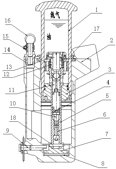
[0015] An airbag-type decelerator, which consists of: the speed valve plate 13 connected to the piston rod 5 in the decelerator slide cylinder 1, the high-pressure upper chamber formed by the decelerator slide cylinder and the piston rod, The left side of the housing has an exhaust pipeline connected to the air bag 16, and the housing has a return air pipeline connected to the air bag. The lower chamber of the sliding cylinder of the decelerator is connected to the hydraulic oil pump, and the hydraulic oil pipeline is equipped with a return valve. The sliding oil cylinder of the deceleration top is connected with the helium pump body 2.

Embodiment 2

[0017] According to the air bag-type speed bumper described in Embodiment 1, the exhaust pipe has an exhaust pipe seat 14 on which the air bag 16 is fixed by a throat hoop 15, and the casing The bottom has an adjustment pad 8, and the adjustment pad has a stopper seat 7, and the stopper seat is fixedly connected by a stopper pin 9, and the described stopper seat is connected with the piston rod 5 through a cylindrical pin 18, and the piston A sealing cover 3 is sheathed on the outside of the rod, and the sliding oil cylinder 1 is sheathed on the outer cover of the sealing cover.

Embodiment 3

[0019] According to the airbag type decelerator described in Embodiment 1, the interior of the piston rod is hollow, the base of the piston rod has a pressure regulating screw 6, and the pressure regulating screw has a spring seat 10, and the spring seat There is a spring 4 on it, and the spring has a pressure valve stem 11, and the upper end of the pressure valve stem is connected with the pressure valve seat 12 through a speed valve plate 13 and a speed spring 17, and the speed valve plate and the speed spring are sequentially set on the speed valve seat.


PUM


Abstract

The invention relates to an airbag retarder and a retarding method employing the same. An exhaust system of a common retarder is open to the outside; the common retarder mounted on a field steel rail throughout the year often encounters severe weather such as rain, water may enters an exhaust pipe and flows into the retarder, and the inside of the retarder rusts; in case of heavy snow, the exhaust pipe may be blocked by the snow; at low temperature, the exhaust pipe is frozen and fail to normally exhausts. The airbag retarder comprises a piston rod (5) in a sliding cylinder (1); a speed valve plate (13) is connected to the piston rod (5); the sliding cylinder and the piston rod form a high-pressure upper cavity; the left side of a housing is provided with an exhaust line connected with an airbag (16); the housing is provided with a return line connected to the airbag; a lower cavity of the sliding cylinder is connected with a hydraulic oil pump; a return valve is mounted on a hydraulic oil pipeline; the sliding cylinder is connected with a helium pump. The airbag retarder is applicable to retarding.

Description

Technical field: [0001] The invention relates to an airbag type deceleration top and a deceleration method. Background technique: [0002] The decelerator is a speed control tool that can automatically control the speed of the vehicle without external energy. It can be used in straight and curved sections in the yard for purpose braking. It consists of two parts, the sliding cylinder assembly and the shell assembly, which are fastened on the outside of the rail with stud bolts. Inside the sliding cylinder, there is a speed valve for judging the speed of the vehicle and a pressure valve for braking the vehicle. , and filled with a certain volume of oil and nitrogen. Therefore, the retarder does not decelerate vehicles below the critical speed, but only decelerates vehicles above the critical speed. [0003] The earliest retarder in the world was developed by British Dowty Company in 1958, while our country began to study the retarder in 1974. With the help of Harbin Institu...

Claims


Application Information

Patent Timeline
Patent Type & Authority Patents(China)
IPC IPC(8): B61K7/02
CPCB61K7/02
Inventor 李清艳郝素红关亚男许龙伟
Owner 哈尔滨东安铁路设备制造有限公司
Why Eureka
Try Eureka