
Automatic storage system and access method of friction roller

A technology for storage and friction rollers, applied in general control systems, control/regulation systems, storage devices, etc., can solve problems such as slow speed, complicated access process, and low efficiency

Inactive Publication Date: 2016-08-17
HEFEI XINSHENG OPTOELECTRONICS TECH CO LTD +1
View PDF8 Cites 0 Cited by
  • Summary
  • Abstract
  • Description
  • Claims
  • Application Information

AI Technical Summary

Problems solved by technology

[0005] Embodiments of the present invention provide an automatic storage system and access method for friction rollers, which can solve the technical problems of complex access process, slow speed, and low efficiency

Method used

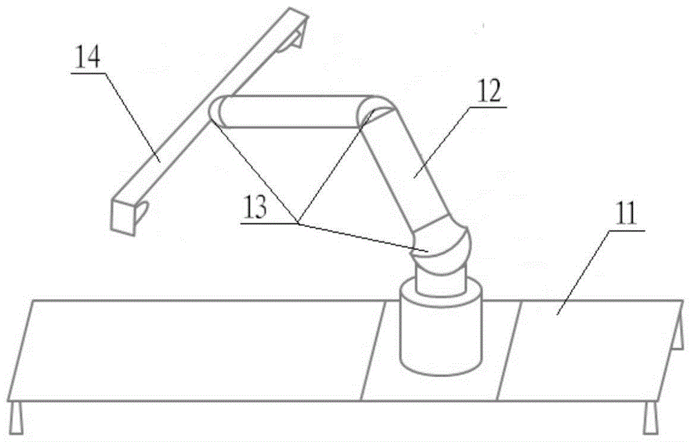
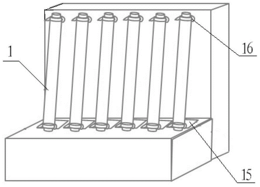
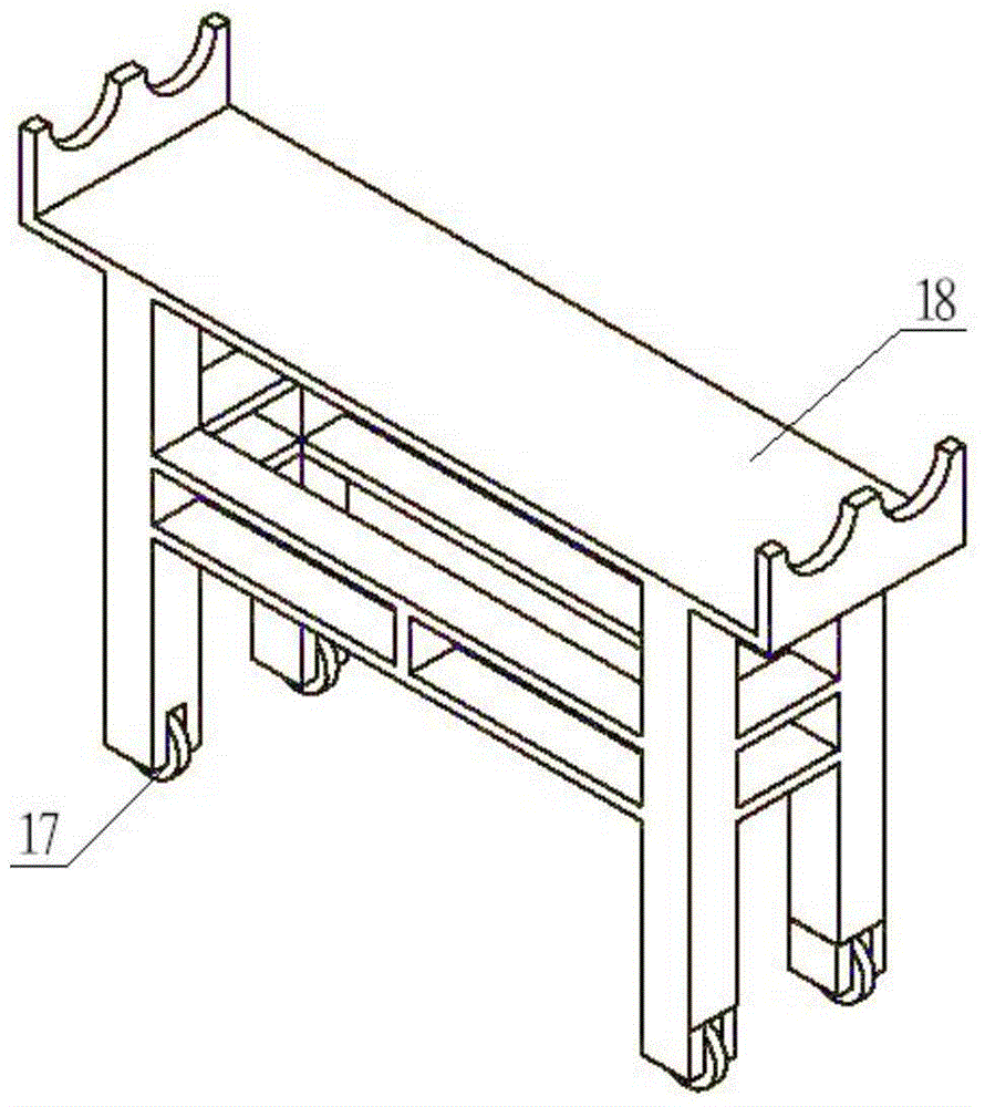

Image

  • Automatic storage system and access method of friction roller
  • Automatic storage system and access method of friction roller
  • Automatic storage system and access method of friction roller

Examples


Embodiment 1

[0057] This embodiment is an automatic storage system for friction rollers, comprising a roller storage device 2, a roller transport track 3, a roller transport platform 4 and a positioning device 5, such as Figure 4-Figure 7 shown.

[0058] The roller storage device 2 includes a rotatable storage roller main body 20, such as Figure 6 and 7 As shown, one end of the storage roller body 20 is connected to the first bracket 201, and the other end is connected to the second bracket 205. The first bracket 201 and the second bracket 205 are fixedly installed on both sides of the roller track 3, and the first bracket 201 is provided with The first motor 202 capable of driving the rotation of the storage roller main body 20; in addition, one end of the storage roller main body 20 is provided with at least two first clamping members 213 uniformly distributed in the circumferential direction, and the other end of the storage roller main body 20 is provided with the first The clampin...

Embodiment 2

[0075] This embodiment is an automatic deposit and retrieval method for the friction roller by using the automatic storage system for the friction roller in the first embodiment above. The automatic roller storage operation process includes in sequence: fetching the roller, transporting the roller and storing the roller.

[0076] Roll taking: the control unit sends instructions to the transmission device (roller motor 406) between the roller platform 4 and the roller track 3, and the transmission device (roller motor 406) will drive the roller platform 4 to move along the roller track 3 to At the corresponding position of the friction machine device 6, the transmission device obtains an instruction to stop the transmission; subsequently, the first lifting device (for example, the above-mentioned cylinder 407) will drive the roller table 402 to move upward to a certain height after obtaining the instruction issued by the control unit; then , the automatic roller unloading device...


PUM


Abstract

The invention discloses an automatic storage system and an access method for friction rollers, which include a roller storage device, a roller transport track, a roller transport platform and a positioning device; the roller storage device includes a roller storage main body, first and second brackets and a first Motor; one end of the roller storage body is provided with a first clamping member, and the other end is provided with a second clamping member; the roller transport platform includes a sliding seat and a roller setting platform, and a transmission device is provided between the roller transport track and the sliding seat; positioning The device includes a sensor and is electrically connected to a control unit. In the automatic storage system of the friction roller, the roller transport platform transports the friction roller to the bottom of the roller storage device under the action of the transmission device, and accurately positions it, and then a pair of clamping parts clamp the friction roller; the invention can Realize the automatic access function of the friction roller, shorten the access work time, and improve the access efficiency; in addition, this vault system does not need to manually pick and place the friction roller, nor does it require the use of robots, which can save a lot of manpower and reduce production and Maintenance costs.

Description

technical field [0001] The invention relates to the technical field of box forming technology of liquid crystal panels, in particular to an automatic storage system and an access method for friction rollers used to process the surface of an alignment film. Background technique [0002] In the box-forming process of liquid crystal panels, the rubbing process refers to rubbing the surface of the alignment film on the substrate with a certain direction and strength with a rubbing roller (Roller) wrapped in nylon cloth or cotton cloth, so that it can form a film that can orient the liquid crystal. Alignment and pre-tilt grooves, this process is called liquid crystal molecular alignment technology. The quality of the orientation effect directly affects the quality of the liquid crystal display, so the orientation technology has extremely high requirements on the rubbing roller. In addition to the material of the rubbing roller can affect its quality such as precision and deformat...

Claims


Application Information

Patent Timeline
Patent Type & Authority Patents(China)
IPC IPC(8): B65G37/00B65G43/00B65G47/04B65G35/00B65G47/90G02F1/1337
CPCB65G1/10B65G1/137G05B15/02
Inventor 王文浩黄助兵洪艳平
Owner HEFEI XINSHENG OPTOELECTRONICS TECH CO LTD
Learn More