
A combustion beam for lime kiln with air cooling device

An air-cooled, lime kiln technology, applied in the field of combustion beams with an air-cooling device, can solve the difficulty in processing a high-temperature and wear-resistant thermal insulation layer or a wear-resistant layer, and it is difficult to process the high-temperature wear-resistant thermal insulation layer or wear-resistant layer. Fixed installation, high temperature resistant wear-resistant heat insulation layer or wear-resistant layer processing, high installation cost, to achieve the effect of low cost, simple structure and improved service life

Active Publication Date: 2019-04-05
苏州朗信智能科技有限公司
View PDF5 Cites 0 Cited by
  • Summary
  • Abstract
  • Description
  • Claims
  • Application Information

AI Technical Summary

Problems solved by technology

Both of the above-mentioned patents have the following problems: it is difficult to reliably install the high-temperature wear-resistant heat insulation layer or the wear-resistant layer on the combustion beam body; The size of the installation hole of the combustion beam on the existing kiln body is adjusted; the processing of the high temperature and wear-resistant heat insulation layer or the wear-resistant layer is relatively difficult; the materials, processing and installation costs of the high-temperature and wear-resistant heat insulation layer or the wear-resistant layer are compared High; there is a risk that the entire combustion beam needs to be repaired or replaced after the high temperature and wear-resistant insulation layer or the wear-resistant layer is partially damaged

Method used


Image

  • A combustion beam for lime kiln with air cooling device
  • A combustion beam for lime kiln with air cooling device
  • A combustion beam for lime kiln with air cooling device

Examples


Embodiment Construction

[0026] The principle, structure and specific implementation of the present invention will be further described below in conjunction with the accompanying drawings.

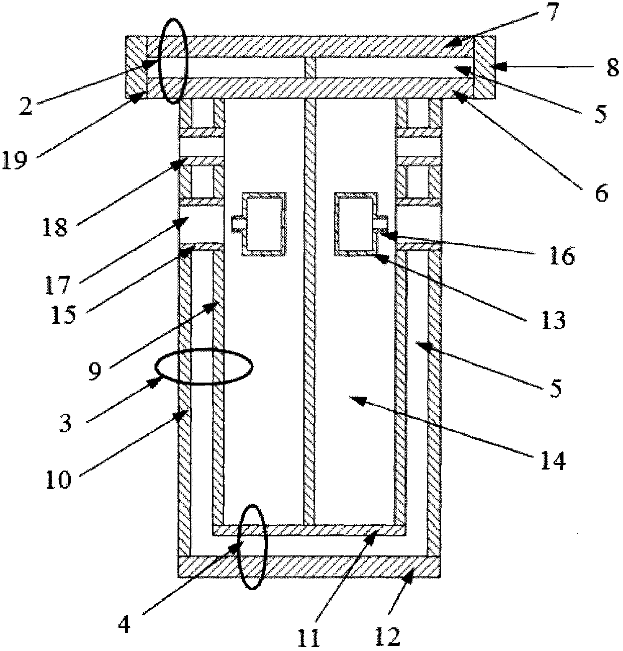
[0027] figure 1 A schematic cross-sectional view of a combustion beam for a lime kiln with an air cooling device provided by the present invention, as can be seen from the figure that a combustion beam for a lime kiln with an air cooling device includes a beam body (1) and a The fuel pipeline (13) and the burner (17) inside the beam body (1); the beam body (1) is composed of the beam body top wall (2), the beam body side wall (3), and the beam body bottom wall (4), Beam top wall (2), beam body side wall (3), beam body bottom wall (4) define air channel (14); beam body top wall (2), beam body side wall (3), beam body bottom wall (4) is a hollow structure with a cooling medium circulation cavity (5); the beam top wall bottom plate (6), the beam top wall panel (7), the beam top wall side plate (8) define the beam to...


PUM

PropertyMeasurementUnit
decomposition temperatureaaaaaaaaaa

Abstract

The invention provides a combustion beam provided with an air cooling device and used for a lime kiln. The combustion beam comprises a beam body, and a fuel pipeline and a burner which are located in the beam body, wherein an air channel is limited by the beam body; the burner comprises a fuel burner arranged on the fuel pipeline, and a combustion-supporting air pipeline which is arranged on the position, corresponding to a fuel nozzle, of the beam body and is communicated with the air pipeline; a cooling air pipeline is formed in the upper side or the periphery of the beam body and is communicated with the air channel; sprayed air can be used for effectively cooling a top wall of the beam body and preventing high-temperature flame from being in direct contact with the part, particularly the crossed part of a bottom side plate of the top wall of the beam body, so that the ablation effect is reduced; furthermore, the brushing effect on the top wall of the combustion beam by particles clamped in the airflow sprayed out from the burner can be weakened so that the service life of the combustion beam is prolonged; the cooling air pipeline is easy to machine and the total structure size of the combustion beam is not changed; a mounting hole in the combustion beam of an existing kiln body does not need to be adjusted and the combustion beam can be directly mounted on the existing kiln body.

Description

technical field [0001] The invention belongs to the technical field of combustion equipment, and relates to a combustion beam for a lime kiln, in particular to a combustion beam with an air cooling device. Background technique [0002] The beam type lime kiln has a series of advantages such as low cost, low energy consumption, strong production capacity, large working flexibility and wide fuel adaptability, and is widely used in lime production for metallurgy, chemical industry and other purposes. When using a beam-type lime kiln for lime production, raw materials such as limestone fall from the top of the kiln, pass through the preheating zone, calcination zone, and cooling zone in the kiln body in sequence, and finally output from the discharge port at the bottom of the kiln. The decomposition temperature of limestone is about 900°C, and the calcination temperature is between 1000°C and 1200°C, and the calcination is mainly completed in the calcination area with a higher t...

Claims


Application Information

Patent Timeline
Patent Type & Authority Patents(China)
IPC IPC(8): C04B2/10
Inventor 张增华孔繁光王慧钟海胜
Owner 苏州朗信智能科技有限公司
Learn More